My final project for the week was to use a 4x4 keypad matrix, and a rotary encoder with switch.
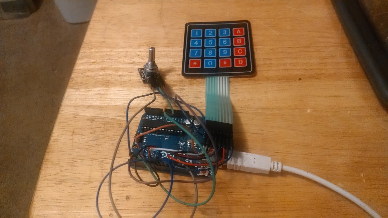
The 4x4 16 Key matrix is pretty easy to use, it does take 8 I/O lines, but works well, and the code to make it work is pretty small. A lot of information about it can be found here:
I did end up modifying the code slightly, They were using a Mega, but I think the code would have needed to be modified slightly even if they had hooked up a UNO. 1st they used Pin 13 twice (one time to turn on/off the LED, and again they used it to read the keypad, this of course didn’t work). SO I ended up moving the line from pin 13 to pin 5. Next thing it’s not as clear as it could be which pins on the keypad to hook to which pins on the arduino.
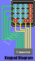
I am going to use his picture and try to explain it a bit better:
1 2 3 4 5 6 7 8
as you can see there are 8 pins on the keypad. Looking from the left to the right lets # them 1 to 8, (I made the picture bigger, so it looks distorted, and my numbers may or may not line up the way I want, but I tried).
I am using an UNO, but from what I can tell this should work on any variation of Arduino.
Keypad Pins
|
Arduino Pins
|
1
|
9
|
2
|
8
|
3
|
7
|
4
|
6
|
5
|
5 (This is my modification)
|
6
|
12
|
7
|
11
|
8
|
10
|
This setup seems to work with the (modified) sketch and library found on the website.
My other modifications were an addition of pinMode(13, OUTPUT); to set the Led, the * and # on the keypad will turn on and off the LED, this seemed to be a needed change with the way the sketch was written.
The sketch setups an array with the numbers and letters in the “correct” locations, as you push a button it reads the ROWs and COLs and then using the array it outputs the number or letter.
/* Keypadtest.pde
*
* Demonstrate the simplest use of the keypad library.
*
* The first step is to connect your keypad to the
* Arduino using the pin numbers listed below in
* rowPins[] and colPins[]. If you want to use different
* pins then you can change the numbers below to
* match your setup.
*
*/
#include <Keypad.h>
const byte ROWS = 4; // Four rows
const byte COLS = 4; // four columns
// Define the Keymap
char keys[ROWS][COLS] = {
{'1','2','3','A'},
{'4','5','6','B'},
{'7','8','9','C'},
{'*','0','#','D'}
};
// Connect keypad ROW0, ROW1, ROW2 and ROW3 to these Arduino pins.
byte rowPins[ROWS] = { 9, 8, 7, 6 };
// Connect keypad COL0, COL1 and COL2 to these Arduino pins.
byte colPins[COLS] = { 5, 12, 11, 10 };
// Create the Keypad
Keypad kpd = Keypad( makeKeymap(keys), rowPins, colPins, ROWS, COLS );
#define ledpin 13
void setup()
{
// digitalWrite(ledpin, HIGH);
pinMode(13, OUTPUT);
Serial.begin(9600);
}
void loop()
{
char key = kpd.getKey();
if(key) // Check for a valid key.
{
switch (key)
{
case '*':
digitalWrite(13, LOW);
break;
case '#':
digitalWrite(13, HIGH);
break;
default:
Serial.println(key);
}
}
}
|
Above is my modified code.
The Rotary switch is something a little different, from this website, http://bildr.org/2012/08/rotary-encoder-arduino/
it’s output this a 2 digit binary code, that will go 00, 01, 10, 11, so if you are rotating the switch and starting at 01 you can either have a 00 or 11 depending on direction of the switch. so by adding the previous encoded value to the beginning of the current encoded value we get 1 of 8 possible numbers (0001, 0010, 0100, 0111, 1000, 1011, 1110, 1101) 1101, 0100, 0010, 1011 all mean clockwise movement, 1110, 0111, 0001, 1000 are all counter-clockwise. Easy enough, now we just need to read the switches, The sketch uses interrupts to handle this, and it seems to a good way to handle it.
While the website, explained how these worked pretty well, it didn’t have hook up instructions for the encoder Jim got, it took a little trail and error, but since are only 5 pins, it wasn’t that hard to figure out.

As you can see in this picture it’s pins are labeled,
2 of the labels ended up making since:
GND - Ground & SW - is the Switch (Pin 4 on the Arduino)
Rotary Switch Pin
|
Arduino
|
Gnd
|
ground
|
+
|
2
|
SW
|
4
|
DT
| |
CLK
|
3
|
The rotary encoder Jim got has a switch, so I used the code for that section.
One line of code did need to be changed, In void loop() the if(digitalRead(encoderSwitchPin2).... should just be (encoderSwitchPin)... That was the only error I found in the code.
//From bildr article: http://bildr.org/2012/08/rotary-encoder-arduino/
//these pins can not be changed 2/3 are special pins
int encoderPin1 = 2;
int encoderPin2 = 3;
int encoderSwitchPin = 4; //push button switch
volatile int lastEncoded = 0;
volatile long encoderValue = 0;
long lastencoderValue = 0;
int lastMSB = 0;
int lastLSB = 0;
void setup() {
Serial.begin (9600);
pinMode(encoderPin1, INPUT);
pinMode(encoderPin2, INPUT);
pinMode(encoderSwitchPin, INPUT);
digitalWrite(encoderPin1, HIGH); //turn pullup resistor on
digitalWrite(encoderPin2, HIGH); //turn pullup resistor on
digitalWrite(encoderSwitchPin, HIGH); //turn pullup resistor on
//call updateEncoder() when any high/low changed seen
//on interrupt 0 (pin 2), or interrupt 1 (pin 3)
attachInterrupt(0, updateEncoder, CHANGE);
attachInterrupt(1, updateEncoder, CHANGE);
}
void loop(){
//Do stuff here
if(digitalRead(encoderSwitchPin)){
//button is not being pushed
}else{
//button is being pushed
}
Serial.println(encoderValue);
delay(1000); //just here to slow down the output, and show it will work even during a delay
}
void updateEncoder(){
int MSB = digitalRead(encoderPin1); //MSB = most significant bit
int LSB = digitalRead(encoderPin2); //LSB = least significant bit
int encoded = (MSB << 1) |LSB; //converting the 2 pin value to single number
int sum = (lastEncoded << 2) | encoded; //adding it to the previous encoded value
if(sum == 0b1101 || sum == 0b0100 || sum == 0b0010 || sum == 0b1011) encoderValue ++;
if(sum == 0b1110 || sum == 0b0111 || sum == 0b0001 || sum == 0b1000) encoderValue --;
lastEncoded = encoded; //store this value for next time
}
|
The above code has been modified.
My next step was to make both the Keypad & the Rotary Encoder work together, I combined the code from both, made a couple of small changes to how the rotary encoder worked, you now can change the rotary switches, but the changes are not displayed until you push the switch button. The keypad will work with out the button being pushed, and the LED on pin 13 will turn on and off with the use of * and # keys.
This is what I came up with:
/* Keypadtest.pde
*
* Demonstrate the simplest use of the keypad library.
*
* The first step is to connect your keypad to the
* Arduino using the pin numbers listed below in
* rowPins[] and colPins[]. If you want to use different
* pins then you can change the numbers below to
* match your setup.
*
*/
#include <Keypad.h>
int encoderPin1 = 2;
int encoderPin2 = 3;
int encoderSwitchPin = 4; //push button switch
volatile int lastEncoded = 0;
volatile long encoderValue = 0;
long lastencoderValue = 0;
int lastMSB = 0;
int lastLSB = 0;
const byte ROWS = 4; // Four rows
const byte COLS = 4; // four columns
// Define the Keymap
char keys[ROWS][COLS] = {
{'1','2','3','A'},
{'4','5','6','B'},
{'7','8','9','C'},
{'*','0','#','D'}
};
// Connect keypad ROW0, ROW1, ROW2 and ROW3 to these Arduino pins.
byte rowPins[ROWS] = { 9, 8, 7, 6 };
// Connect keypad COL0, COL1 and COL2 to these Arduino pins.
byte colPins[COLS] = { 5, 12, 11, 10 };
// Create the Keypad
Keypad kpd = Keypad( makeKeymap(keys), rowPins, colPins, ROWS, COLS );
#define ledpin 13
void setup()
{
// digitalWrite(ledpin, HIGH);
pinMode(13, OUTPUT);
Serial.begin(9600);
pinMode(encoderPin1, INPUT);
pinMode(encoderPin2, INPUT);
pinMode(encoderSwitchPin, INPUT);
digitalWrite(encoderPin1, HIGH); //turn pullup resistor on
digitalWrite(encoderPin2, HIGH); //turn pullup resistor on
digitalWrite(encoderSwitchPin, HIGH); //turn pullup resistor on
//call updateEncoder() when any high/low changed seen
//on interrupt 0 (pin 2), or interrupt 1 (pin 3)
attachInterrupt(0, updateEncoder, CHANGE);
attachInterrupt(1, updateEncoder, CHANGE);
}
void loop()
{
if(digitalRead(encoderSwitchPin)){
//button is not being pushed
}else{
Serial.println("Rotary Encoder Button Pushed");
//button is being pushed
Serial.print("Rotary Encoder: ");
Serial.println(encoderValue);
delay(100); //just here to slow down the output, and show it will work even during a delay
}
char key = kpd.getKey();
if(key) // Check for a valid key.
{
switch (key)
{
case '*':
digitalWrite(13, LOW);
break;
case '#':
digitalWrite(13, HIGH);
break;
default:
Serial.println(key);
}
}
}
void updateEncoder(){
int MSB = digitalRead(encoderPin1); //MSB = most significant bit
int LSB = digitalRead(encoderPin2); //LSB = least significant bit
int encoded = (MSB << 1) |LSB; //converting the 2 pin value to single number
int sum = (lastEncoded << 2) | encoded; //adding it to the previous encoded value
if(sum == 0b1101 || sum == 0b0100 || sum == 0b0010 || sum == 0b1011) encoderValue ++;
if(sum == 0b1110 || sum == 0b0111 || sum == 0b0001 || sum == 0b1000) encoderValue --;
lastEncoded = encoded; //store this value for next time
}
|
So there you have it, a whole week of Binary and BCD!
Kd8Bxp'S Blog: 20140625 4X4 Keypad Matrix And Rotary Encoder With Switch >>>>> Download Now
ReplyDelete>>>>> Download Full
Kd8Bxp'S Blog: 20140625 4X4 Keypad Matrix And Rotary Encoder With Switch >>>>> Download LINK
>>>>> Download Now
Kd8Bxp'S Blog: 20140625 4X4 Keypad Matrix And Rotary Encoder With Switch >>>>> Download Full
>>>>> Download LINK eL