Tuesday, December 18, 2018

A 100 meter lidar (?) Maybe not.....

100 Meter LiDAR Range Sensor
Found this unit on Aliexpress, for around $32 dollars, it was probably used as an electronic tape measure. The thing that peaked my interesting was the 100 meter range (328 feet or so). It is easy to use, and seems to work well, but so far I've not gotten anywhere close to the 328 feet. (32.8 feet is about the best I've seen so far)
Could this be a miss print on the listing, or could I just be using this wrong (?) ......
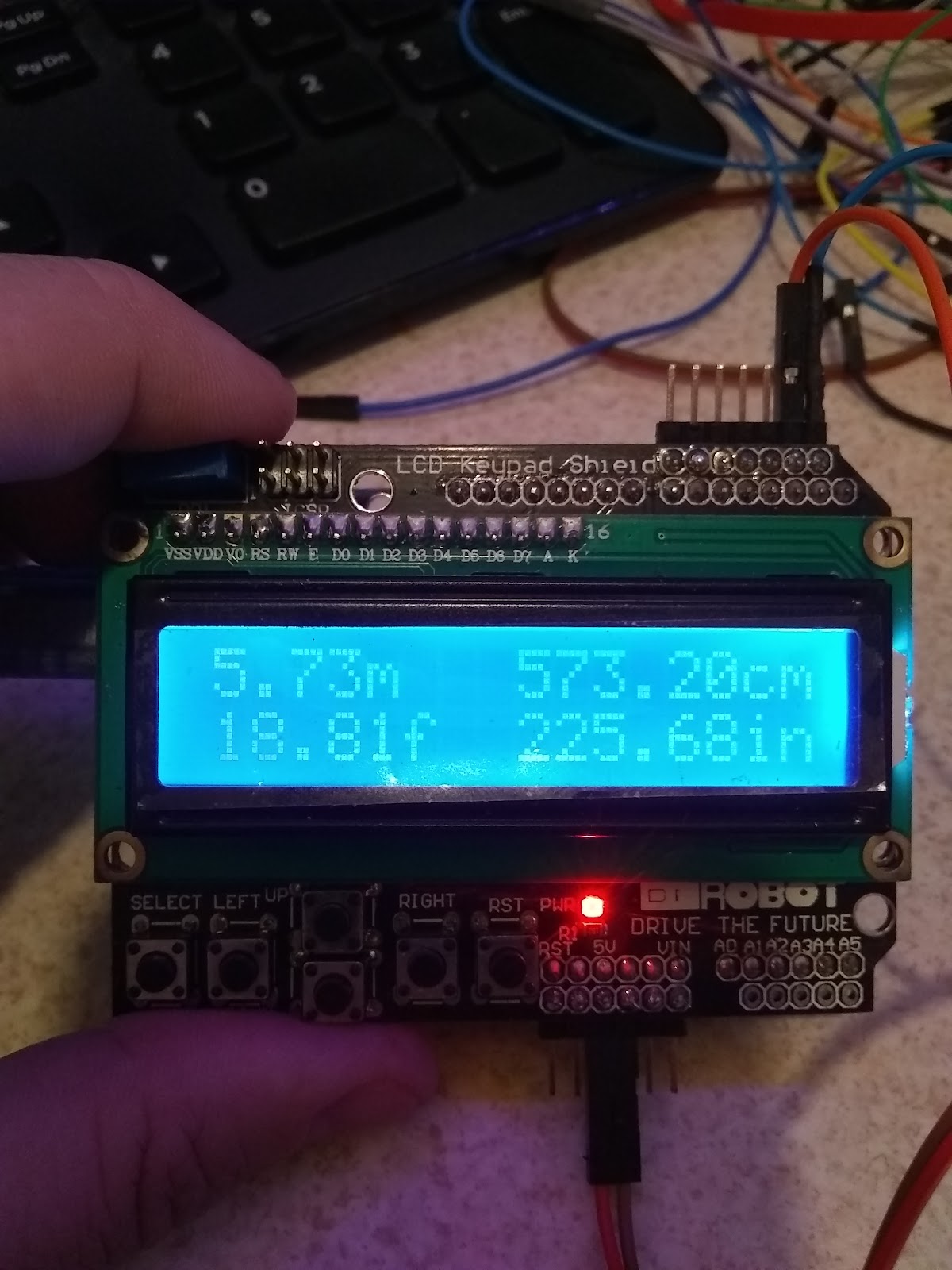
Well either way, I've set this up to work with an Arduino Uno - so far I'm just displaying the distance on a DF Robot 1602 LCD/w buttons.
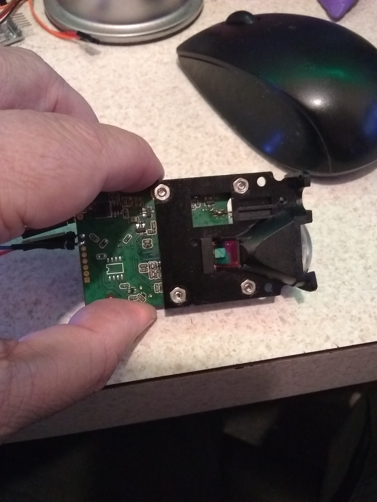
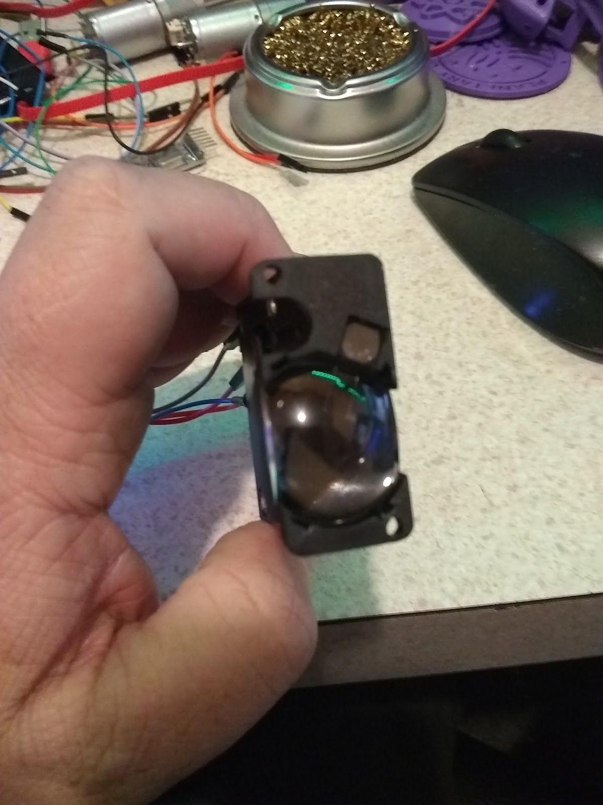
Laser Type: 635nm, 1 mw (red)
Range: 0.02 to 100 meters
Typical accuracy: +/- 2mm (0 to 40, indoor 20 meters white walls; through correction can be up to +/- 1.5mm)

The laser can be turned on or off (assuming for aiming reasons), reads can be “automatic”, fast (less accuracy), and slow (more accuracy) - “automatic” appears to be about medium speed.
The laser can also display it’s temperature and voltage levels. The output of the sensor is in the format of a String, a typical reading may look something like this:
“12.345m,0079” which tells the distance, and signal quality.  Signal quality a lower number is better. This is good for display, and easy to use for display, but it’s a problem if we need to compare the numbers, or if we are using this on a robot and need the robot to stop at a distance.
Luckily - there is a way to remove the unwanted information from a string, and turn that string into a float - it’s not pretty, and a lot of code to do it, but it can be done.
In my demo, I’ve converted the distance from meters to feet to cm to inches. I’ve dropped the signal quality - but it can be pulled out and used as well.
The demo, will display if the laser is on, or off, the temperature and voltages (default temperature is Celsius, and I convert it to Fahrenheit), formatted for the display I am using.
I’ve setup 5 buttons, one for normal reading, one for fast, one for slow - one will toggle the laser on or off, and one will display voltage, temperature.
An expanded demo would be to use this on a robot for distance/obstacle avoidance.
(under my less than scientific tests, I’ve only been able to get a reading of 32.x feet or about 10 meters - anything greater than 32 feet gives either a reading that is just wrong, or an error. Is it possible that I have a bad unit, or that it really is 10 meters not 100 meters (which would mean it was listed wrong to start with)? )

Wednesday, October 10, 2018

Merge two GIT repositories to ONE.

Recently I wanted to merge two GIT repositories into one.  The main reason for this was the two projects were different, but closely related, sharing much of the same code.  And I just thought it would be easier if everything was together.

So I did what any normal person does, I googled it.  Turned out this is easier to do that I thought it would be - the results are easy to find on google - but I thought I'd share my use case - not only might it help someone else - But it will help me when I want to do this again - I willn't have to search, I can just look at my blog :-)

This posting on stackoverflow asks the question perfect:
https://stackoverflow.com/questions/1425892/how-do-you-merge-two-git-repositories

Question:
"Consider the following scenario:
I have developed a small experimental project A in its own Git repo. It has now matured, and I'd like A to be part of larger project B, which has its own big repository. I'd now like to add A as a subdirectory of B.
How do I merge A into B, without losing history on any side?"
The Best Answer:
If you want to merge project-a into project-b:
cd path/to/project-b git remote add projectgit remote add project-a path/to/project-a git fetch projectgit fetch project-a git merge
git merge --allow-unrelated-histories project-a/master # or whichever branch you want to merge git remote remove project-a 
This method worked pretty well for me, it's shorter and in my opinion a lot cleaner.
Note: The --allow-unrelated-histories parameter only exists since git >= 2.9. See Git - git merge Documentation / --allow-unrelated-histories
This also worked pretty well in my case, I ran into one conflict - so off to google again to find how to resolve that (again, GIT makes it pretty easy to deal with the conflict)
https://help.github.com/articles/resolving-a-merge-conflict-using-the-command-line/

This needs to be read - but the basics of it the arrows in the file show where the conflict is, and from which branch the conflict came from.  And the equals is the dividing point.
So you might see something like
If you have questions, please
<<<<<<< HEAD
open an issue
=======
ask your question in IRC.
>>>>>>> branch-a

Decide if you want to keep only your branch's changes, keep only the other branch's changes, or make a brand new change, which may incorporate changes from both branches. Delete the conflict markers <<<<<<<=======>>>>>>> and make the changes you want in the final merge. In this example, both changes are incorporated into the final merge:
If you have questions, please open an issue or ask in our IRC channel if it's more urgent.
Add or stage your changes: git add *
and commit the changes with a comment:
git commit -m "resolved merge conflict"

There are other cases covered by the github help competing changes to a file that deal with complete file conflicts

Monday, September 10, 2018

DF Robot micro:Maqueen Robot For BBC Micro:Bit (programmed with the Arduino IDE)

DF Robot micro:Maqueen Robot
For BBC Micro:Bit (programmed with the Arduino IDE)
Sep 10, 2018


Prerequisites:
  1. Arduino IDE 1.8.x (recommend 1.8.5) installed and setup for your machine. https://www.arduino.cc/en/Main/Software
  2. Install the Arduino-nRF5 board core. Follow the instructions here: https://github.com/sandeepmistry/arduino-nRF5
  3. Install the Adafruit Micro:Bit Library: https://github.com/adafruit/Adafruit_Microbit and learn more about it here:  https://learn.adafruit.com/use-micro-bit-with-arduino
  4. Finally install the arduino-BLEPeripheral library (either from the library manager or by following instructions here: https://github.com/sandeepmistry/arduino-BLEPeripheral  ) * Note be sure it’s the one from sandeepmistry if you are using the library manager *
  5. NewPing Library (Which I believe is this library) https://github.com/eliteio/Arduino_New_Ping and is only needed if you are going to use an ultrasonic.

For this project you will need at least one Micro:Bit Controller:

And the Maqueen Robot chassis: https://www.dfrobot.com/product-1783.html

The Micro:Bit is setup to use Microsoft:MakeCode or Scratch and Python.
The Sandee P Mistry Board core lets us use this board with the Arduino (C style) language as well.

General Information:
I used the general information that is found either in the Maqueen MakeCode library on the board itself, or from trial and error to come up with something that works (mostly) with the Arduino IDE.

Working (or mostly working):
  1. Motors (I2C interface, easier to port than I thought it would be)
  2. Line Sensors (P13, P14)
  3. Ultrasonic (using newping library) P1, P2 * Attempted to get this working without the library, but it failed (????) *
  4. 2 LEDs P8, P12
  5. Buzzer P0 - *  tone is not yet implimented with the board, analogWrite works but doesn’t sound great, bit bang also works, but doesn’t sound great - this is in the mostly working columb)
What’s not working: (These things work if you use MakeCode, but so far I’m unable to get them to work with Arduino).
  1. NeoPixels (P15 4 pixels) - The Adafruit Neopixel library appears to be the only library that supports the Micro:bit, this isn’t surprising. But I’ve not been able to get it work on P15, it does work on P2 which is what the example provided is using. https://learn.adafruit.com/micro-bit-lesson-3-neopixels-with-micro-bit/software
  2. IR receiver (P16) - so far I am unable to get this to work at all - *I need something that doesn’t mess with interrupts or timings, but I think that is a big ask for this device*
  3. Communication between two Micro:bit controllers - It’s a bit upsetting to me that such a basic thing was neglected in the Arduino IDE (If this does work, and you have supporting code please share - I have not been able to get this to work, or find any code that claims it works) ** This is a basic thing in the MakeCode, I’ve not been able to find the library they use or information about how they make it work **  https://learn.adafruit.com/micro-bit-radio-controlled-puppet/code-the-two-micro-bits    


Basic Sketches:  (To be duplicated)
  1. Drive and turn - (done) I2CMotortest, I2CMotortest2
  2. *RGB Breathing Ambient Light - unable to complete at this time.
  3. LED Light Flash - (DONE) - blinkdemo
  4. Read Ultrasonic Distance  (*DONE*) - They output to the LED Matrix, I output to the Serial console of the Arduino IDE (Easy to change as needed) newping
  5. *Read Infrared Key Assignments - unable to complete at this time. *
  6. *IR Remote Control - unable to complete at this time*
  7. Line Tracking - Currently Working on it.
  8. Ultrasonic Obstacle Avoiding - (DONE) - avoid
  9. Light Operated Sprite (unsure about this one)
  10. Wireless Remote Control  - * They are using a Micro:bit Gamepad (see below), I believe I can make this work with the Tablet and Adafruits Bluefruit LE Connect software * This is a work in progress.

The compass and accelerometer on the Micro:bit also work, as well as the LED Matrix and the two buttons on it.  *The Compass is in the wrong orientation to be used as a true compass, but it maybe able to be used to do relative positions, I will have to test that more.*

I am in the process of making a library and attempting to duplicate the applications in the DF  Robot wiki. It is not even close to being ready. I’ll post a link when it is ready.

DF Robot also provided a Micro:Bit Gamepad for use with this project, the gamepad has 8 buttons total (various P#s), a LED on P16, buzzer on P0, and a vibration motor on P12
Button assignments:
DOWN  - P13
LEFT - P14
UP - P8
RIGHT - P15
X - P1
Y - P2
A - P5
B - P11

This was very easy to port over to the Arduino IDE, the buttons are all HIGH until they are pushed then they go LOW.
I may not be able to use this as intended because I am having problems getting two Micro:bit to communicate directly with each other.

A game or something may be coming thou...we will see

Friday, June 29, 2018

Using the Mediatek LinkIt One board with Linux and Arduino IDE (1.8.5)

Using the Mediatek LinkIt One board with linux and Arduino IDE
June 29, 2018

By piecing together a couple of instructables, and a “answer” from stackoverflow. And a couple of things of my own, I was able to get “Blink” to work on the LinkIt One board using Arduino IDE 1.8.5 - most of the thanks goes to user v-i-s-h from instructables Who provided most of what is needed.
Both of these instructables where written by v-i-s-h.

They mostly work as written - if you take the 1st one, STEP 1 and STEP 2 then start on the 2nd instructable, when that is done move back to the 1st for STEP 4 and 5. It mostly works.

On Arduino IDE version 1.8.5 you will get compile errors, which can be fixed using the information found here:
User Alan Wootton has the correct answer - you will still get compiler warning, but it works.
I got it to work by editing platform.txt
and adding core/ so that it reads:
{build.path}/core/syscalls_mtk.c.o
instead of
{build.path}/syscalls_mtk.c.o
platform.txt was located in:
/Users/awootton/Library/Arduino15/packages/LinkIt/hardware/arm/1.1.17
answered Dec 16 '15 at 0:04
111


STEP 1 - Install the LinkIt One core into the Arduino IDE,

v-i-s-h has provided a core url that will work on linux machines.
https://raw.githubusercontent.com/v-i-s-h/LinkIt-One-Linux-Arduino-Support-/master/package_vish_linkItOne_linux_index.json

You will have to make a few changes, so you’ll need to go into the hidden “.arduino15” directory that should be in your home folder. You are looking for the packages directory under .arduino15
So it will look something like this:
/home/{user}/.arduino15/packages
You’ll want to find the LinkItOneLinuxArduino directory.

STEP 2 - in the tools/linkit_tools/1.1.17 directory

“/home/{user}/.arduino15/packages/LinkItOneLinuxArduino/tools/linkit_tools/1.1.17”
We need to make the scripts executable by issuing the command
chmod a+x *.sh
  ***DON’T REPLACE THE platform.txt file yet, there is a new version that uses  the updated “packtag.py” tool.

--So now we jump over to the 2nd Instructable.

STEP 3 (STEP 1) Get the updated packtag.py package.

And you’ll copy or move this file to the linkit_tools/1.1.17 directory from the previous step.
And you’ll need to make the python script executable.
chmod +x packtag.py

STEP 4 (STEP 2) Download the new platform.txt

You’ll need to right click on the link and then save as - if it doesn’t have the name platform.txt - rename it.
Replace the platform.txt found in
“/home/{user}/.arduino15/packages/LinkItOneLinuxArduino/hardware/arm/1.1.17” with the file you just downloaded - remember it needs to be called “platform.txt”

Important - Restart the IDE!

Now we can jump back to STEP 4 and STEP 5 from the original instructable.

STEP 5 - Blink The Built in LED.

Make sure to select the Linkit One from the board manager, look for the blink example (standard Arduino example)
*** NOTE The LinkIt One doesn’t define  LED_BUILTIN (The board core was written long before this became a standard thing to do) ***

The easiest way to fix this is at the top of the sketch add the line:
#define LED_BUILTIN 13

Or can also replace all the LED_BUILTIN with the number 13.

At this point, this is where the instructable kind of gets a little lost and confusing, So here is what I learned.
You need to save the modified version of your sketch (To compile sketches for this board you need to have a saved copy somewhere that you can get to easy).

On my system, the LinkIt One enumerates as two serial ports, /dev/ttyUSB0 and /dev/ttyUSB1 (of course those could change depending on what else I have plugged in.)
And apparently the device could show up as /dev/ttyACM1 and /dev/ttyACM0
What I found is compile the sketch, you need to have the board plugged in, it will fail to upload, but that is ok because we are not going to compile the sketch the way we would with a “normal” Arduino board.
To compile - click on the “Sketch -> Export” tab in the IDE,
In your sketch directory (This is why you need to save it somewhere), you will find a binary called “app.vxp”

Now we need to switch the LinkIt One from UART mode to MS mode - what I’ve found about this is the battery for the LinkIt One needs to also be installed and on….
(this could just be me).
Besure to make the mode change with the power removed.

Once you restart the LinkIt One, a small 10Mb removable drive should show up.
You are going to copy the “app.vxp” file to the MRE folder on the removable drive.

*** A ONE TIME STEP IS NEEDED ***
In the root of the LInkIt One drive you’ll see an ‘autostart.txt’ file, and you’ll need to edit it and point it to the app.vxp file, not the test.vxp file it is pointed at.
This should be on the 2nd line of the file, and it should look something like:
App=C:\MRE\app.vxp

You only need to do that once.

Disconnect your LinkIt One, (make sure battery is off as well, no power) - put it back in UART mode, and you should see the LED blink (or your sketch run on it).

That’s about it.