20140620 BCD Demo using 10 bit Mini Level switch
I think most people in the group know what Binary and BCD are, but for those that don’t. BCD - Is an encoding system to represent decimal numbers with a fixed number of bits, usually 4.
In a Binary system, the bit place holders goes something like this:
…., 128, 64, 32, 16, 8, 4, 2, 1 and can go on forever. In a BCD system you are limited to the 1st 4 bits (or last 4 bits depending on how you look at it)
So BCD:
8, 4, 2, 1 (In BCD each bit must have a value of either 0 or 1 in it. In a standard Binary system zeros are needed to the least significant bit so in my example if you wanted to write a decimal number of 37 in binary it would look like this:
100101 notice that it’s assumed that place holder 128 and 64 are zero in this example. AS well as anything above 128 (512, 1024, ect))
IN BCD you are limited to 4 bits, SO the maximum decimal number that can be represented is 15. (8 + 4 + 2 + 1), that would be great if we used a based 16 (hex) number system, but we use base 10 (decimal) so really all BCD can do is represent decimal numbers from zero to 9.
Each encoder will then represent a place vaule in a decimal system but MUST BE 4 Bits long, all for BITS must be either zero or a 1: For example if I wanted to represent decimal 1 in BCD (4 BIT) it would look like this: 0001, and decimal 2 would look like this 0010 BCD.
SO a Decimal 37 in BCD would look like:
0011 0111 BCD notice how it is different from a Binary 37 (100101 Base 2) in BCD each digit is converted to a bit binary code each digit is represented by four bits. Normally started with the MSB (3) ending with the LSB (7) in this case.
Here is the truth table:
BCD vaules ->
|
8
|
4
|
2
|
1
|
Dec Vaules 0
|
0
|
0
|
0
|
0
|
1
|
0
|
0
|
0
|
1
|
2
|
0
|
0
|
1
|
0
|
3
|
0
|
0
|
1
|
1
|
4
|
0
|
1
|
0
|
0
|
5
|
0
|
1
|
0
|
1
|
6
|
0
|
1
|
1
|
0
|
7
|
0
|
1
|
1
|
1
|
8
|
1
|
0
|
0
|
0
|
9
|
1
|
0
|
0
|
1
|
So the 1st part of this demo is just some power going into the common on the switch, 10 leds going to ground, and the switch hooked to each LED, to represent the 10 bits of the switch.
It’s not hooked to a microcontroller at all, and just shows what is really going on,
the next step will be too hook the encoder up to an Arduino, and display the numbers on the switch.
I’ll update this when I have a simple video of my 1st part up on youtube, I’ll need to take that apart to add the microcontroller, so probably will not get demoed at the meeting.
As a third thing, I am going to use the real time clock and make a “Binary” Clock, these clocks are really BCD clock as each digit of the clock is represented by a set number of BITS.
They general display time in 24hr notation. So you end up with something that looks like this:
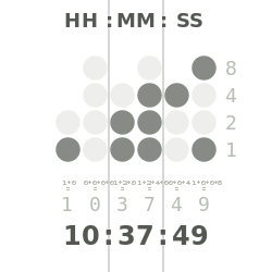
each row represents a digit from a clock, you read each row as a number.
No comments:
Post a Comment