Tuesday, April 7, 2015

4/1/2014 HC-05 Bluetooth device

Apr 1, 2014    HC-05 Bluetooth device
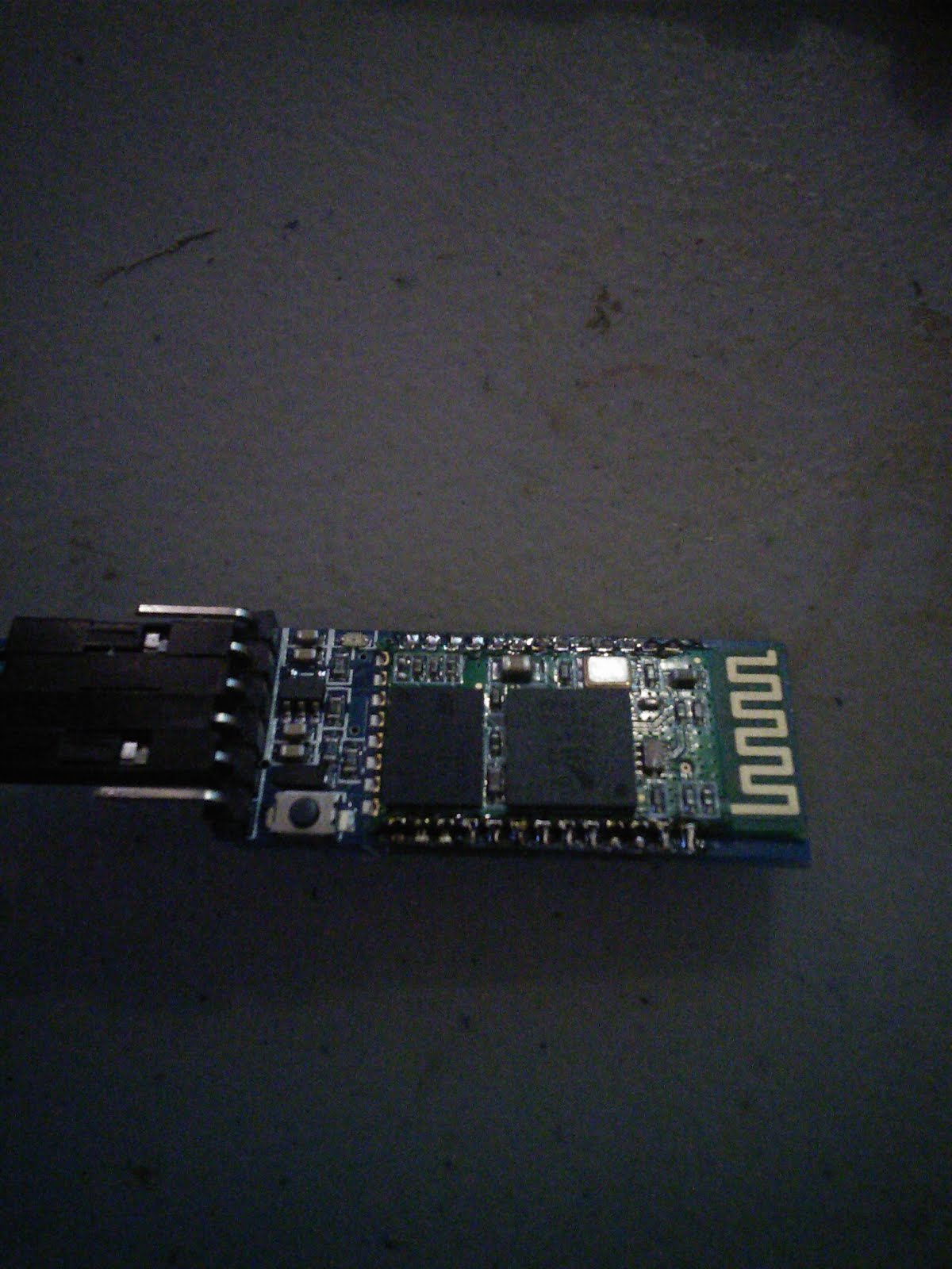
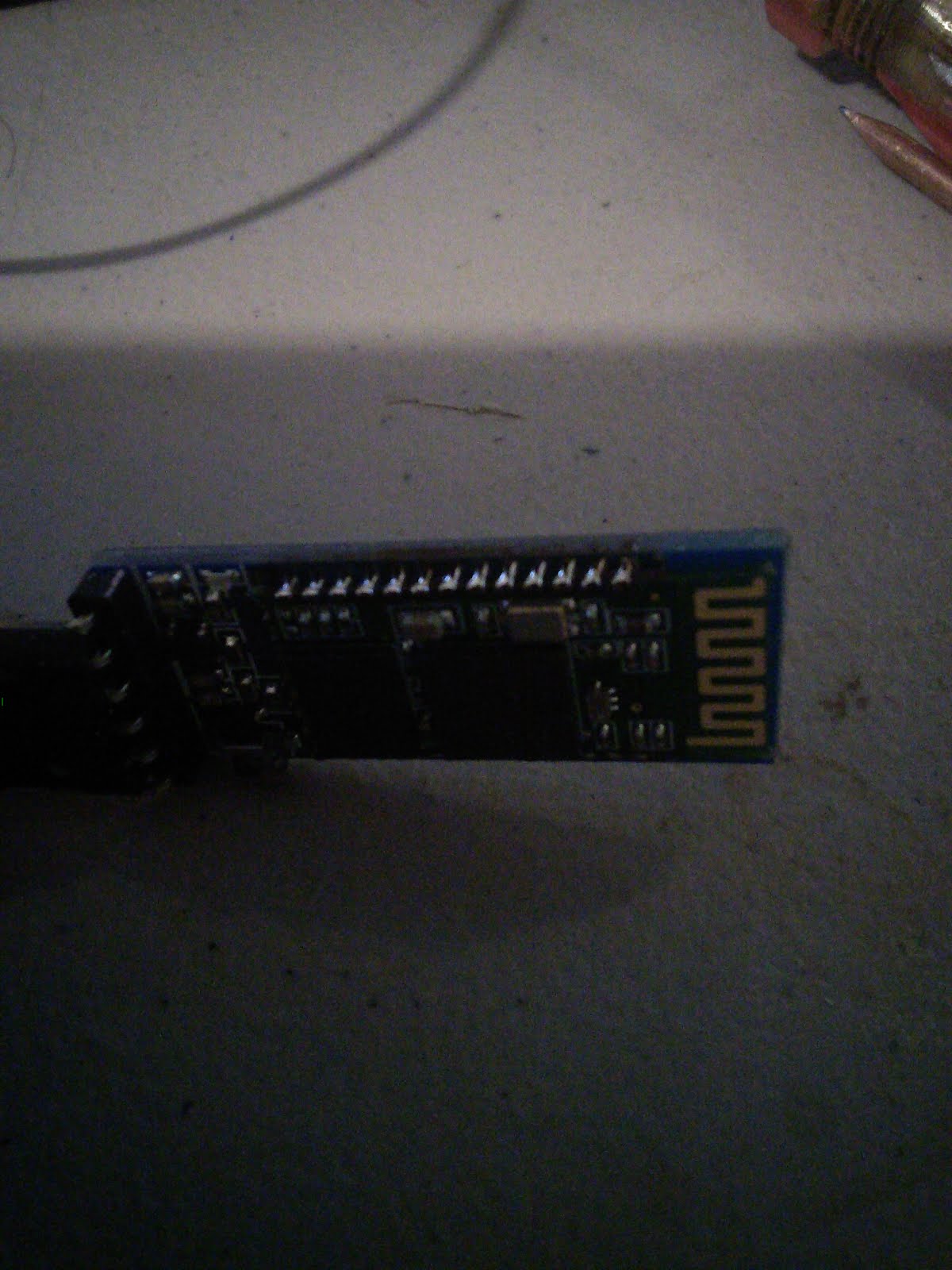
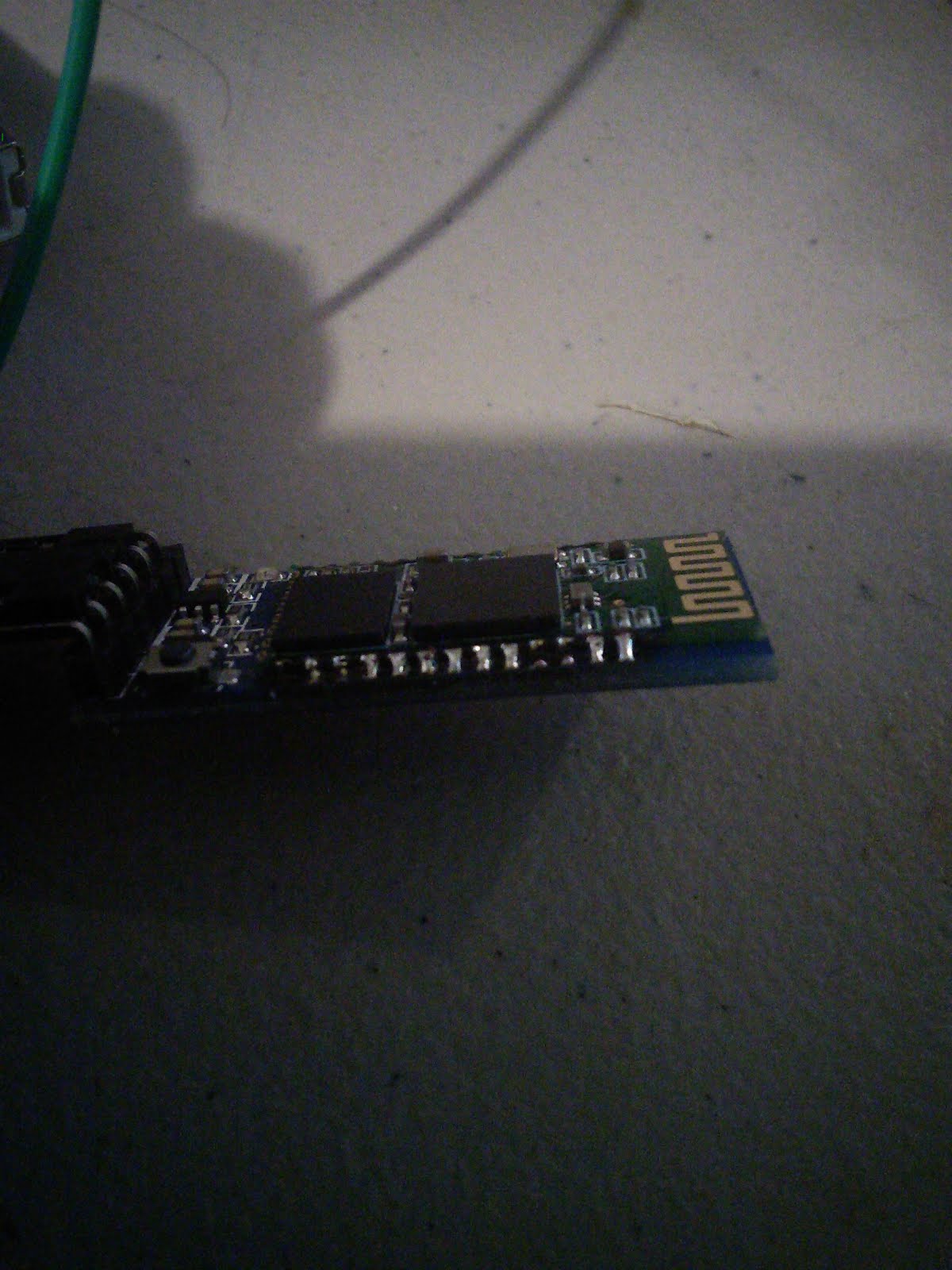
At the 1st meeting I attended Jim gave me a blank holder for the HC-05 Bluetooth device, I was able to solder a HC-05 to it today, and it worked well.
The HC-05 bluetooth is a surface mount style device, and that can be a little scary for people.
They are cheap enough, and the blank is cheap enough I figured if I messed it up I wasn’t out much.  You aren’t saving yourself much by soldering your own to the blank (I think .30 or .35 cents, spend the extra money and get one already mounted).
I used the “drag” method of soldier, which is only one method for doing surface mounts, but I’ve got to say, it was easy to do, and it works, and it works well.

You’ll see in a couple of the pictures below that I didn’t get every pin, on this it doesn’t matter, I got the pins that are connected and as I said the bluetooth does work well.


3/22/2014 Cheap FS100a 433 Mhz Transmitters Revisited


Mar 22, 2014  CHEAP FS1000a 433mhz transmitters revisited,

Hooked up two transmitters and one receiver.  One Arduino was set to transmit “hello #1”, One Arduino was set to transmit “hello #2”, and one Arduino set to receive, Seems to work fine!

here’s a video:


So I was giving it the worse case, and the best chance to fail, and it seemed to work. By that I mean, both transmitters were right next to each other, the receiver was only a less the a foot away, and I put antennas on everything.
I don’t know for sure, but I had suspected this would work. I think it’s because of the modulation type, but I’m not sure about that either (not 100% sure).  A lot of digital modulation types have built in error checking.  
These are cheap, and a cheap way to send low speed data around.


3/16/2014 The SPO-512 Speech Synthesizer

Mar 16 - 17, 2014
A side project this week, The SPO-512 Speech Synthesizer also known as the RoboVoice from SpeechChips.com http://www.speechchips.com/shop/item.aspx?itemid=22

This is a PIC microcontroller that takes a serial 9600 baud input (ASCII data) and outputs (speaks) VOICE, There are a couple of demos of this on the website. I bought the chip probably 2 years ago, and it sat on my desk.  There is a design circuit in the PDF on the site, turns out most of the circuit is an amplifier for the speaker, the circuit to make this work is really pretty simple. 4 grounds, and 4 3.3v power - a TX line, a RX line, a Cap for filtering (I think, left it off and it didn’t sound as good, I also didn’t have the 4.7u cap that is called for, I used a 10u, seems to be fine so I think it is just filtering) and an output to the speaker.  

I have a lot of parts that I pulled out of old computers, turns out a few of the dell systems have little tiny amplified speakers build in them, these things work great, and I wish I would have pulled more out.  I am running my little speaker off 5v, but I wonder if it wasn’t hooked up to 12v in the computer - seems like they were much louder. Doesn’t matter it works, and I think it will work at 3.3v as well.

I think I’ve talked to the man who invented this chip, I think he is very active in the “Basic Stamp” forums, and very knowledgable about all things microchip.

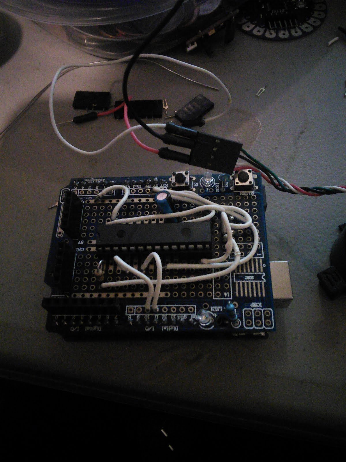
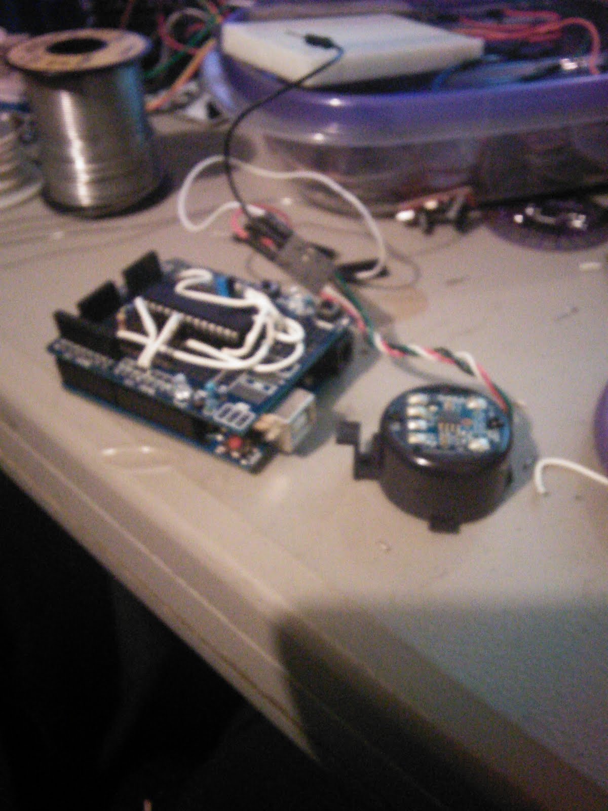
Speech chips offered a robovoice on an arduino shield, I don’t think they do any more. So after I went from breadboard, I moved the whole thing over to a proto board, (well the speaker isn’t mounted, I really wanted to mount it, but…)
So here are a few pictures of my side project, and I’ll bring it with me to the meeting on Thurs.

It took a couple of hours to move it from breadboard to proto board, and I ran into a couple of issues, the 1st, the chip is 28 pin, the board only had enough multi-tap pins for a 20 pin microchip, (Issue was fairly easy to overcome). 2nd my proto board didn’t give any tap to the 3.3v line of the arduino, in fact it was shorted to the 5v line (Huh?) Yeah that was a mistake from the manufacturer I am sure, but I can see how someone not paying attention could short out the Arduino board.  This proto board provide 3 different 5v rails, and 3 different ground rails, (one set of those rails ended up being UNDER the IC chip and not at all in a useful spot), No 3.3v rail, I had to make my own. but that ended up taking up more room on the board then really needed. I could have done without one of the 5v rails for a replacement of a 3.3v rail, probably would have had to move the IC but I could have dealt with that.
My last issue was - this proto board had stackable header on it. I wanted to make this semi-permanent so I didn’t want to plug a wire into the header, I wanted to use the port directly. I had to remove the most of the headers which caused another problem, it was a little hard to remove the headers, and the holes closed behind being removed, for some reason my solider sucker just wasn’t working well tonight.  
Over all thou, this was a fun project, now I just need to order a couple more protoboards for the next time I want to move off breadboarding.


3/15/2014 NRF24L01-2-4GHz-Antenna-Wireless-Transceiver-Module

Mar 15, 2014
nRF24L01 Demo!

Actually there are several different libraries for this device, the one above is what the Arduino.cc website uses in it’s examples.

This one seems to support more of the features of the nRF24L01
this one also supports the Raspberry PI, and a few of his examples have the rPI and Arduinos “talking” to each other

One other library I found is: http://www.airspayce.com/mikem/arduino/NRF24/
Airspayce also has the library for the “cheap” RF transmitters and receivers, good side, lots of information about wireless protocols and types.

Cheapest I’ve found these amazing tranceivers:

There are a number of forums and people talking about how they feel these will replace Zigbees which were the leader in Arduino and wireless technology. Mostly because of the cost of a Zigbee and the costs of these. There are at least 2 different models, the ones I have don’t have a + at the end, I’m not sure what the difference between them is.  There are also a couple of different configurations for the boards themself, https://www.sparkfun.com/products/691 (19.95 + shipping) even at that price they are cheaper then Zigbee.

I’ve read some mixed reviews on power - opted to go with 3.3v in mine, but 5v seems ok
General Specs on these:
3.3v (I would stick with 3.3v just to be save) It’s also possable my boards have a regulator on them
100m range at 250kbps
250kbps to 2Mbit data rate (This puts the safely in the DSL range, although low end DSL http://testmy.net/tools/connection_chart.php) making it “high speed”
Auto Acknowledge (The RF24 library says this can be turned off if needed)
Auto Re-Transmit (believe this can be turned off as well)
Multiceiver capable (Arduino’s library doesn’t support this from a few of the forums I’ve read, I think the other 2 libraries do) (Up to 6 Data Pipes)
32 Byte separate TX and RX FIFOs
5v tolerant input pins
Software selectable channels from 2.4Ghz to 2.525Ghz (125 Selectable channels)
SPI interface
11.3mA TX at 0 dBm output power
13.5mA RX at 2Mbps air data rate
900nA in power down

more information about the chip itself can be found here:
Lot of support on Nordic Semiconductor website (the makers of this fine chip)

I was trying to get full duplexing to work, but it was difficult to type on two keyboards at once
From looking at the code, it appears that (not in multiceiver mode) you setup a TX channel, and a RX channel, so I think they should be full duplex.

I am going to be demoing the NRF24 library, and running the “Chat” program, which was a little tricky to setup at first, it seems it needs a Line Feed or CR in order to send data.

Should be interesting, I’ll also have the other libraries loaded on the laptop, and we can look at some of the example code.  

3/8/2014 Arduino Uno bootloader and the Mifare RFID reader/writer RC522

Mar 8, 2014

RFID - what is it? How does it work? what can you do with it? and how to use RFID with an Arduino. RFID is a wireless non-contact use of electromagnetic fields to transfer data. With the uses of Identifying and tracking inventory, or other objects. There are several standards in use with RFID, too many to go into here. There is also active RFID and Passive RFID, passive is probably the most common. Active RFID has a greater range. RFID tags can contain information and be both read from and written too (Depending on the tag, and which version of tag you have.)

This is not a new technology, having origins dating back to 1945. A “modern” passive radio transponder with memory was 1st patented in 1973, this would be the great grand father of modern RFID.  RFID works in several different frequencies, with probably the most common (at least consumer level) being 13.56 MHZ (HF) using the MIFARE ISO/IEC 14443 standard, but other frequencies include 120 -150 kHZ (LF) which is currently unregulated, 433 Mhz (UHF) Short Range Devices also used for defence and active tags, 865 - 868 Mhz in Europe & 902-928 Mhz in North America and using various standard
2.4 to 5.8 Ghz - this is also various standards, and active RFID 3.1 to 10 Ghz requires semi-active or active tags and appears to not be fully implemented at this time.

A “new” type of RFID is currently the defacto standard, and is being wildly used in cell phones and tablets - Near Field Communication (NFC) - NFC is ISO/IEC 14443.  NFC tags generally speaking can hold more information then there early RFID counterparts. You can also find NFC/RFID in a lot of credit cards, any place you see a card reader that you just have to tag is using RFID. The Middletown Library and I would think the West Chester branch use RFID tags in their books, they have for years but I’m not sure why they do it.

How does RFID work?
It’s really pretty simple (as easy as 123) - Remember in school you probably learned about Magnetic lines of force (magnetic poles North and South), probably you also remember that when a current is passed through a coil you can create a electro-magnet. And when you put that near another coil of wire you INDUCE a voltage on the 2nd coil? Well that is how this works, the RFID reader has a coil, that is powered on making a little electromagnet probably not
strong enough to pickup any thing, but still it’s there. The tags are also coils, and by passing thetag in front of the reader you INDUCE a voltage. The tags also have a chip in them that contains a tiny transceiver, and an ID code (each tag has a unique code, thou you can clone tags if needed, not going into how to do that beyond the scope). Depending on the tag it may contain other information as well. The reader also has a transceiver in it and receives information when
the tag transmits. In passive system the tag needs to be pretty close to the reader, In an active system the tag can be a few feet to a few hundred feet away from the reader.  Which brings us to what can you do with RFID?
Alot really, one of the big things is tracking, and managing inventory, Everything in the store has an RFID tag, you pickup an item and walk out the store, the active scanners at the door - buzz - the system knows you didn’t pay for that item because it didn’t get scanned at the checkout. (OK, that’s just one example) I think this is probably why the libraries have RFID tags in the books, but I don’t know why they don’t use them for check ins/check outs (They also have
bar codes on the books for check in/check out) Any way, off on a little tangent there.  Already said above, visa/master card/amex all have started to put RFID chips in credit cards for Fast Pay (NFC) BTW you can use your NFC enabled cell phones for fast pay if you have your account attached to your phone.
The auto industry has been using RFID tags for years, in both the manufacture and parts replacement in cars. - A new car is sitting on the line waiting to have a door, using an active tag the robots can find out what is missing, what color and just about anything else about the car it’s making - updating the tag, and moving down to the next robot in the line. Parts bins are marked with RFID tags so the robots can find them when they are needed.

Other uses, Tagging animals with owner information, toll collection (active readers mostly). and countless other uses. Using RFID with an Arduino:
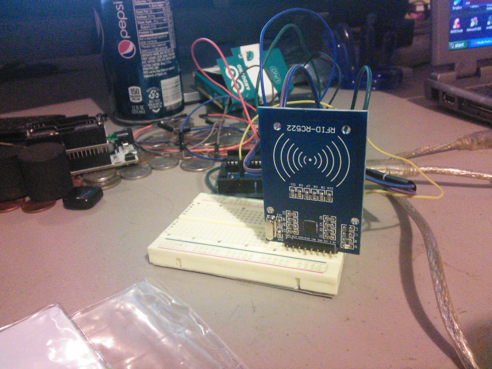
There are many different RFID readers available for the Arduino, they all seem to work the more or less the same. (Some are capable of writing to a tag others are not) Mine is a cheap sub-$5 reader that came with two tags, a Mifare 522 which is one of the most common out there. it uses a SPI interface.
Unfortunately, there is not a whole lot of information out about the model I have, in fact I only found 2 website, both were virtually the same.

https://sites.google.com/site/arduinomega2560projects/home/level-1/arduino-rfid-rc522
and
http://www.grantgibson.co.uk/2012/04/how-to-get-started-with-the-mifare-mf522-an-and-arduino/

There wasn’t a library to use, and I am still trying to make heads and tails out of the code they provided, but I think you send command to the reader in hex and wait for a reply. From what I can tell thou, you pass a tag in front of the reader, and the arduino will send (serial console) the 5 ID strings contained in the tag.
If the right tag is used - It will say “Hello Dave” or “Hello Grant”. One of the sites is also putting a “2” in front of the 1st set of IDs (not sure why but I removed that front the code as it just seemed strange to be there)Both websites also made a mistake about the pin map They have a pin called SS mapped to Arduino pin 10, my board doesn’t have a pin marked SS but the pin marked SAD seems to work. Jeremy is using a RFID reader that is based off a zigbee or works in a zigbee socket, also his has a “real” coil of wire, and his code is very different as well. So each reader must be different.

Here is the link to his setup:
http://www.jeremyblum.com/2011/07/08/tutorial-12-for-arduino-rfid-card-reading/

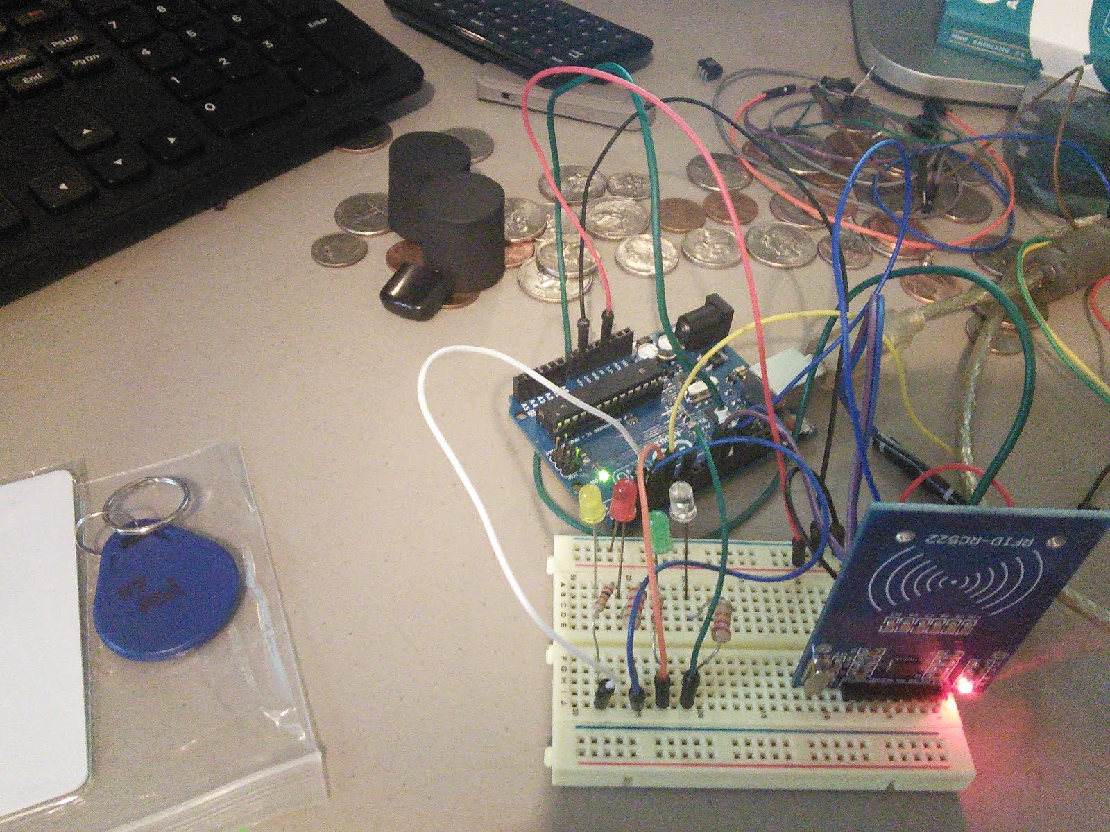
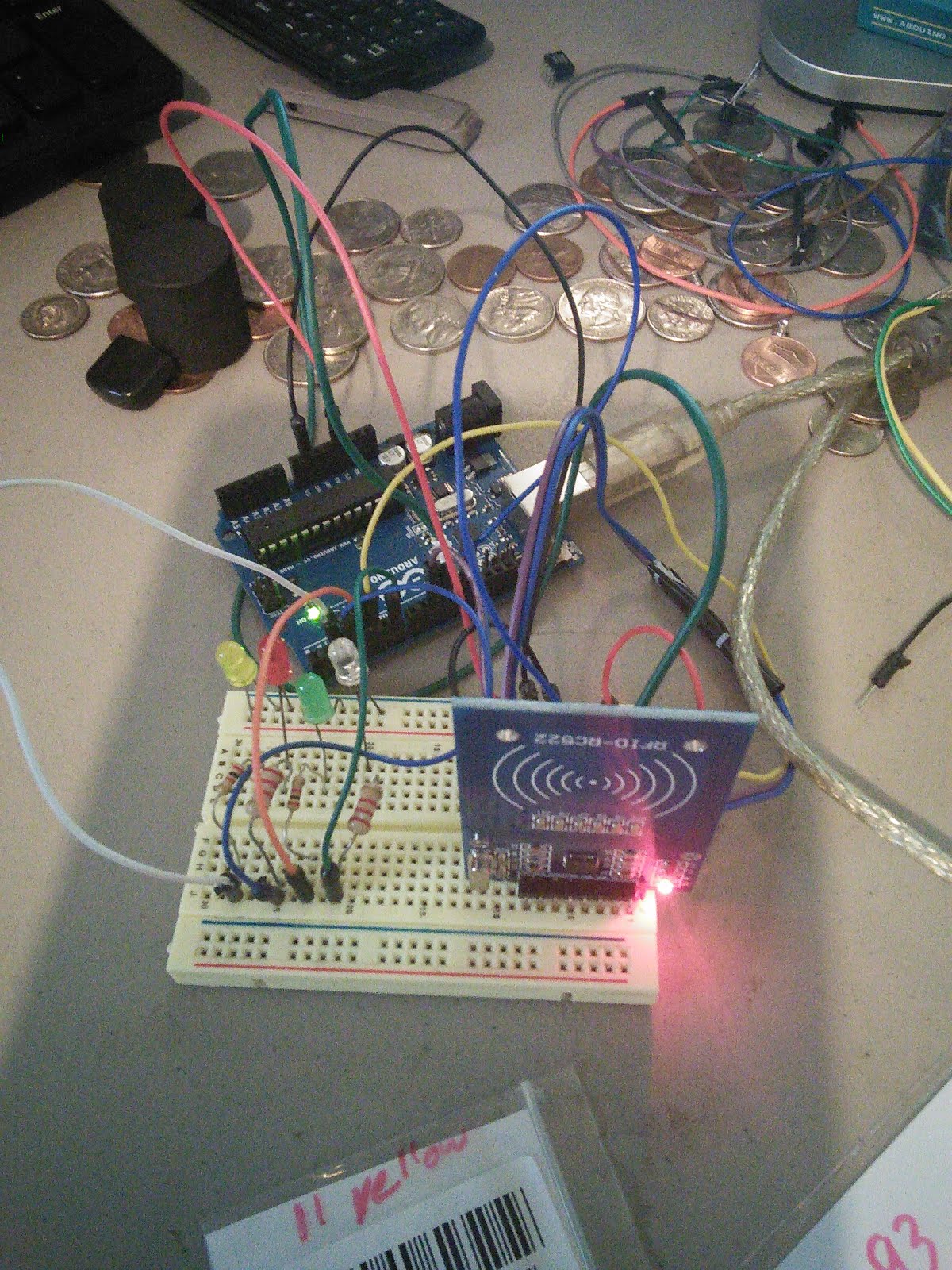
I think by Thursday I will have a demo working that will turn on and off LEDs using various tags I have.

Final thoughts: Most RFID systems need to keep up with the tag ID numbers which would be contained within a database, however it is possible to have simple system with just a few tags (or one that doesn’t need updated often) that doesn’t require a database. And this is the type an Arduino is great for, simple RFID control of lighting or opening a door.

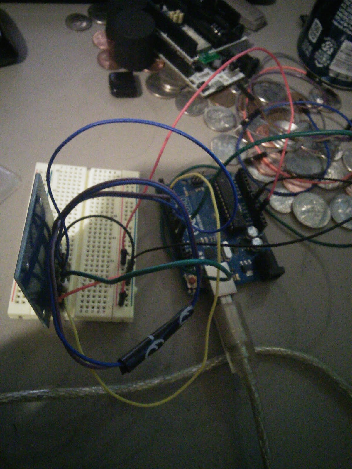
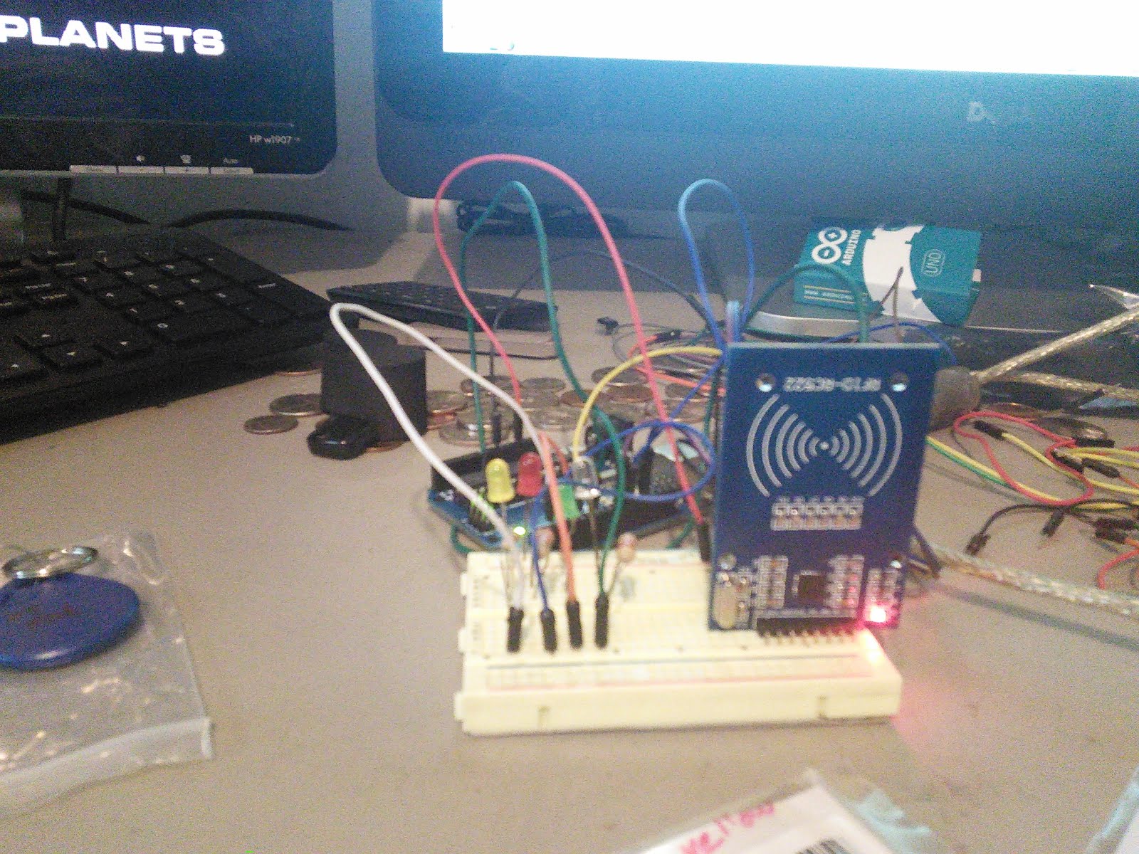
Some pictures of my setup:


20140227 FS1000a 315mhz RX/TX pair

Feb 27, 2014
Initial tests of FS1000a 315mhz RX/TX pair:
This document seems to be relevant to these transmit and receivers.
http://ardumarket.com/en/transmisors/transmisor-rf-fs1000a-330-443mhz-arduino-pic-id19.html
You also need the library from here:
http://www.open.com.au/mikem/arduino/VirtualWire/VirtualWire-1.14.zip
The library contains the sketches found on the page, with the exception that they don’t set the
RX or TX pin
vw_set_tx_pin(3);
vw_set_rx_pin(3);

Also the receiver sketch seems to be a bit different - the example in the library prints out HEX codes.  For the most part these are very simple to use - one Arduino is setup to send information, the other is setup to receive that information - and do something with it.
Modulation type is ASK - or Amplitude Shift Keying - This type of modulation is like AM radio for data So it has some of the same weaknesses and strengths of AM. For more information see:
http://en.wikipedia.org/wiki/Amplitude-shift_keying

Finding a distance for them was a little harder, but as near as I can figure
40 meters or 131 feet indoors, 100 meters or 328 feet in the open.  I tested at about 60 feet inside and it worked without a problem.  Range seems to be dependant on how much voltage you put on the transmitter - from what I
found the TX board can handle between 3 to 12v - with 5v being normal - I don’t know if I trust 12v in this figure, as I only found a couple of sites that said it, and the TX boards were not the same board we have. Better to be safe then sorry and go with 5v.

Like finding a range for these, finding a speed wasn’t as easy as it should be - most sites say between 4800 and 9600 baud work well. A couple of sites say they can go faster, but fastermay cause unreliable data (or no data at all). One site even said that speed was dependant on distance (I don’t think that is right given the type of modulation this uses, but maybe). The sites that have 480 to 9600 baud listed say that it’s a reliable low speed for general use such as reading sensor data.

Impressions of this it would make a good low power data sender for a remote sensor, only takes up one pin, and is really simple to use.

Other information (But not sure if the RX/TX board are the same as what we have):
https://www.sparkfun.com/datasheets/RF/KLP_Walkthrough.pdf
http://www.seeedstudio.com/wiki/index.php?title=315Mhz_RF_link_kit
(Pretty sure this is our board)
http://www.seeedstudio.com/depot/315mhz-rf-link-kit-p-76.html

Update: Feb 28 - Maybe this is not as easy as I first thought, the library seems to have some quirky issues - 1st it seems to want to send a “const char *variable”, I’m not really sure what that is. (Found this out by trying to send a tempature variable floating point to it) and the 2nd thing I found is that it doesn’t work on some of the lesser know Arduino like boards.
(have been trying for the past 2 hours to get the library to work with my Squarewear, wearable temperature sensor, only to find it really doesn’t like that hardware at all) Admittedly the squarewear is not an Arduino, it is closely related to one.

Plans this weekend, try some alternative methods of getting these RF devices to work.

Serious Neglecting the Blog!

So, I haven't been using my blog lately, I think the last post was June 2014.
I have been doing a lot of writing in my google drive about Arduino projects, and other micro controller stuff.

I have been meaning to get back to posting on the blog, but just haven't done it.

So over the next few days, I am going to start moving my documents from drive, and posting them here.

and I'm going to start updating the blog more with projects I am doing.