Monday, June 12, 2017

Raspberry PI Zero W - Speech Synthesizer using MQTT protocol

Raspberry PI Zero W - Speech Synthesizer using MQTT protocol
Jun 12, 2017

The goal of this project is to make a low cost speech synthesizer using text to speech (TTS) for the Arduino or other Microcontroller to use. *And one day voice Recognition*

For the project you need just three things and some time.
  1. Raspberry PI Zero W currently $10.00
  2. 16 or larger Gigabyte SD card with Raspberian installed and configured $7 to $10
  3. Fe-PI Audio sound card (I2S sound) for the Raspberry PI $14
Total Cost: about $34.  

You will spent quite a bit of time setting this up and that maybe worth more than money.

I used the Zero W because in the end I needed it connected to the internet, you could use the Zero but you will most likely want to get it on the net.
A Raspberry PI (model A or B) 1st generation, B+, 2, and 3 should work as well.

I’m not going into how to setup the PI other than the software that needs to be installed.


One of the first things you’ll also want to do is setup the Fe-PI. See my notes here:

  • The Fe-PI is currently supported in the kernel and setup isn’t as bad as it seems.

After you have your SD card setup and the PI booting. And are able to connect to your network. You will most likely want to rename your Raspberry PI from the default name.
Again, I’m not going to go into this as there are hundreds of tutorials on the subject.
I renamed mine to rpi-speak  
Now to connect to the PI with SSH or Web, or MQTT I can use “rpi-speak.local”  
So:
ssh pi@rpi-speak.local will let me ssh into my system with out knowing the IP address.


Next you’ll want to make sure you are up to date.

sudo apt-get update
sudo apt-get upgrade

  • This might take a while, you’ll want to reboot when it done.

You’ll want to install flite - (festival-lite) speech synthesizer. http://www.festvox.org/flite/

sudo apt-get install flite

Once installed give it a test and make sure you hear the audio.
flite -t “Hello World”


*** OPTIONAL STEP ***
Install Apache2 and PHP, Why? At first I thought I would beable to just send a web form and have the PI speak.  It seems that while I was able to execute the commands, everything was being piped to the webpage. And it just didn’t work.
I didn’t uninstall because there are some useful things that can still be done with a web site running on the PI.  But at this point, it’s a optional step, and not needed.
Install instructions:


It was at this point that I still needed away for the Arduino to “talk” to the PI. There are many ways to do this, and here are just a few (I didn’t use).


What is MQTT?

Almost every tutorial on the subject starts off asking this question. Some answers go into great detail, and others are very simple.  I’ll stick with the simple.
MQTT is a machine to machine simple protocol, that uses a publish/subscribe. MQTT uses a BROKER which is really just a server that handles all the messages.

MQTT Brokers can either be public or private, and there are good uses for both.
A Public Broker generally is reachable from any where, and by any one on the internet. Most do provide some type of security.  The draw back however is that anyone/everyone can subscribe to your information. It is unwise to publish sensitive data to a public Broker. Most of the FREE public brokers will not guarantee 100% update.

Here are some public Brokers: (There are many more)
http://www.mqtt-dashboard.com/ (a HiveMQ Dashboard)

I used a Private MQTT Broker, and it’s running on the Raspberry PI.
Mosquitto is a open source, free broker that is easy to install and easy to use.

Here are some tutorials I used to install this, but it comes down to a simple apt-get command on the PI.
sudo apt-get install mosquitto mosquitto-clients python-mosquitto
It’s really that simple, the mosquitto server starts as soon as it’s installed, the mosquitto-clients has the command line commands to publish and subscribe. And python-mosquitto is the library to use MQTT with python.

If you are using linux, you can also install the mosquitto-clients package, and test your install out.

MQTT uses “Topics” - this is how messages are delivered. For my project I use two “topics” - Say and Said (I will probably end up changing at least one of these).
Topics are created by a subscribe or publish to the MQTT Broker.

Here is where it gets interesting thou.
On the Raspberry PI I have a python script running that subscribes to “Say”, and publishes to “Said”. Using the desktop MQTT client I can run one CLI to publish to “Say” and one CLI to subscribe to “Said”. The effect, the two computers can talk to each other.

So with the MQTT (mosquitto broker) running on the PI,
ssh into your pi, and issue the command:
mosquitto_sub -h localhost -t “Say” -v

And issue this command on your desktop.
mosquitto_pub -h rpi-speak.local -t “Say” -m ‘-voice slt -t “Hello I am Sally”’

You should see:
-voice slt -t “Hello I am Sally”
In your SSH window.
So the -h is the host flag, it is the server running the MQTT broker, and can be public or private (such as in this case)
-t is the topic we want to subscribe or publish to “Say”.

It’s really that simple to send a message to a machine running a MQTT subscription.

Once you verify that is working, you’ll need to install a couple of more things, and a python script to get it all working.

Installing paho-mqtt for python.

Type: pip install paho-mqtt on the Raspberry Pi.

I published my python script to github here:

Most of what I learned, I learned from here:
And while he is turning GPIO on and off, it contained enough information to make my “Speech” script.

You will want to copy and paste the script to your Raspberry PI. I just put it in my home directory. “/home/pi/say.py”

You can test the script at this point by typing:
python say.py

And on your desktop, publish a message to the “Say” topic.
mosquitto_pub -h rpi-speak.local -t “Say” -m ‘-t “Hello World!”’

You should hear, the PI say “Hello World”.

We are almost done with the Raspberry PI, we will want to set the script to start when the PI is booted or rebooted.
The easiest way is to setup a cron job. You probably don’t have any cron jobs, yet - so the PI will create a new cron file.
Type: crontab -e to edit the file, and add @reboot python /home/pi/say.py & to the end of the file, save and exit nano, and reboot.  If all goes well when the system is ready - it will say “Ready”
  • Don’t forget to the & at the end of the reboot command.

That is everything you need for the Raspberry PI, at the start of this project I wanted a cheap
speech synthesizer that an Arduino, or other microcontroller could use. So we need to add a MQTT library to the Arduino IDE. There are a number of MQTT libraries, but this tutorial
https://www.baldengineer.com/mqtt-tutorial.html recommends the PubSubClient library.
The easiest way to install is with the “library manager” on 1.6.x and above IDE.
The github for the library is here: https://github.com/knolleary/pubsubclient and the full documentation for it is here:  http://pubsubclient.knolleary.net/

This is a pretty easy to use library, I modified the mqtt_esp8266 example to publish to the “Say” topic, and subscribe to the “Said” topic.  
The only problem I had was the library was unable to connect with the host name “rpi-speak”
Or “rpi-speak.local” and needed an IP address.
This was the only hickup - But being able to SSH into the PI, or using the Webserver and CGI script for the environment (env.sh) it was pretty easy to get the IP address.

My modified sketch can be found here:


Tuesday, May 23, 2017

Generic Raspberry PI 2.2" TFT Screen w/Buttons and IR

Generic 2.2” TFT Screen w/buttons and IR INFORMATION
Or What I learned about the Chinese TFT Screens for Raspberry PI 2 and 3


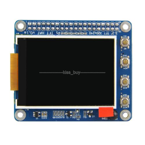
1st Here is the screen I bought from eBay:
Raspberry-Pi-2-3-B-2-2-034-TFT-Screen-LCD-Display-Expansion-Board-Buttons-IR-Sensor


2.2"TFT Screen LCD Display HAT 320x240 for Raspberry Pi 3/2 w/Buttons IR Sensor

Features:

This auction is for a 2.2 inch screen with buttons and IR function for Raspberry Pi 3 and 2 Model B.


Details:

Screen sizing 2.2 inch and supporting a 320x240 resolution with high PPI, being small but able to provide a fine image.

Size: 65mm×56.5mm, standard as a Raspberry Pi HAT board.

Multi-button design: 6 buttons, meeting different demands for buttons from various users

With an Infrared receiver.

Quick-responding technical support for free.


Introduction:

The 2.2 inch screen is a standard Raspberry Pi HAT (hardware attached on top). It supports a 320x240 resolution with high PPI.

Though small, it can display any images clearly. With the 6 buttons on the board, you can define their functions by yourself. And an

Infrared receiver is equipped so you can control the screen remotely.


  • Like Most cheap things, there isn’t documentation provided, and you have to search
  • Also like most cheap things there is a lot of just plain miss leading information.

The key to this display appears to be the fact that it has IR on it. Once I searched “w/IR” I was able to find the same display being sold by Sunfounder (for a liTTYe bit more then you can find on eBay).


Sunfounder provides a Raspberry PI Image and a/or a Python script for setting up the LCD.
(Plus information on how to get the buttons working/IR working)

Their image is based on Raspbian Jessie, and the current OS is Raspbian Pixie
So If you already have a working install (which I did) use the python script to add the needed files and information to your install.

1st thing I learned even the instructions are not quite right. You need to run the python script from the CLI (command line), and as ROOT (sudo).

I answered all the question with the default entries or “y” for yes.

The system rebooted, and the screen (after a liTTYe while) did start to display, and even displayed the “X” server (Thou, my screen is a liTTYe small to use the GUI effectively).

What was a disappoint was it shut the HDMI off and I didn’t get a GUI on it.
But by hitting “CTRL-ALT-F2”, “CTRL-ALT-F4”, and “CTRL-ALT-F6” I was able to get to the command line.


*It was at this point I shutdown the system, unplugged the display, and hoped that it would switch back to HDMI - it did not *
I was still able to get to TTY2,TTY4 and TTY6 - so I could fix the issue from the command line.

Once again I started to google the problem - and once again I can across many people who had the same problem, and a dozen different answers.

Finally I came across this post on Stackexchange

This answer is what worked:
Although this question is very old, I would like to post my answer that I found recently. I am running Raspberry PI 2 Model B with 2.8 PiTFT capactive display. Once I figured out how to get my pitft display to work with Raspberry PI, I could not get Raspberry PI to switch over to HDMI output no matter what I did. Then, I came across this information, which worked for me.
There's two ways to do it. In older Pi installs, use the fb0 framebuffer when you want to display stuff on the HDMI/TV display, for example: FRAMEBUFFER=/dev/fb0 startx will use the HDMI/TV framebuffer for X windows instead of the PiTFT
On Jessie Pi installs, run sudo nano /usr/share/X11/xorg.conf.d/99-fbdev.conf to edit the configuration file and make sure it contains: Copy Code
Section "Device"
Identifier "display"
Driver "fbdev"
Option "fbdev" "/dev/fb0"
EndSection
change the Option "fbdev" "/dev/fb0" line to Option "fbdev" "/dev/fb1" if you want the xdisplay on the PiTFT or fb1 to fb0 for HDMI output.
Update: If don't see the code above in the file, then simply copy and paste what is shown in this answer at the bottom of that file. If you can't find 99-fbdev.conf file in that folder, then there is probably another file with different name like 10-evdev.conf in the same folder which you will have to modify to make it work as described above.
answered Jul 25 '16 at 14:40


The file in /usr/share/X11/xorg.conf.d/ did not exist, and I had to create it.
I didn’t make any other changes or anything to any of the other config files.

Rebooted the system, and sure enough I had X running on the HDMI again.

The TFT screen did boot, but came to a blank screen with a flashing cursor.

** What I learned **
1 It seems TTY1 is on the TFT screen, but linked to X running on the HDMI (in other words what you do in that session seems to have direct effect on X)
2 TTY2, TTY4, TTY6 appear to work on the HDMI
3 “CTRL-ALT-F7” is the X screen on HDMI
4. TTY3, TTY5 appear to work on the TFT screen
5. If you try to start X from TTY1,TTY3,TTY5 the system locks up and displays a bunch of error messages.  Which is fine, X on that small screen was not great anyway.


Wednesday, April 5, 2017

New to Arduino? Recommended Watching

Recently I came across some really good, short videos made by Sparkfun.

They cover a introduction to Arduino from a programming stand point, not a hardware stand point.

Hopefully they do more with some more advanced programming topics but for now:

In no order The videos are:
Arduino Control Flow
Arduino Data Types, Literals, and Variables
Arduino Arithmetic Operators
Arduino Programming Syntax

Tuesday, February 21, 2017

Wicked Devices Nanode with Sketchgarden - How to Flash it to be used as a Arduino UNO


MCM Electronics is selling a Sketchgarden/Nanode board for $10.00.  Unfortunately the idea behind the sketchgarden firmware is long gone.  The board is a older board, but it has a ATMEGA328 and a Ethernet port on it - the headers I believe are not Arduino R3 comparable,  which means that some shield will not work with it, that is still ok.

In order to make the board useful, you have to flash the UNO bootloader on it, because it's a ATMEGA328 and not a ATMEGA328P the usual way to flash the new bootloader doesn't work.

I put together a short (17 min) video of how to flash it, it's not hard to do, but does require some extra steps.


As I said in the video, there isn't a lot of information about the board any more, and here is everything I found and what you may need if you want to flash the new bootloader.

Arduino as ISP
https://www.arduino.cc/en/Tutorial/ArduinoISP

Step 5 & 6 Bootload an Atmega328 by Andy Tallack

https://www.instructables.com/id/Bootload-an-ATmega328/step7/Bootload-the-ATmega328/

Wicked Device Tutorial (Sadly out of date)
http://shop.wickeddevice.com/2013/10/16/nanode-gatewayremote-sensing-tutorial-1/

JeeLabs Ethercard library info
http://jeelabs.org/pub/docs/ethercard/index.html
(This page suggests the CS pin is already PIN 8, the Github repository 
says it's PIN 10, which maybe why I had to change it)
(I think this page is out of date as well)
CS pin is 8 for this board.

Ethercard Library
https://github.com/jcw/ethercard

Friday, January 27, 2017

X-Minus One - A Logic named Joe - My Thoughts.


X-Minus One A Logic Named Joe!


Original a revival of Dimension X, X-Minus was a NBC Radio Drama series, in the early 1950s.
Think Twilight Zone (or The Outer Limits), with no pictures (and arguable worse ideas for episodes).
Actually, if you have been around Sci-Fi at all even if you don't know X-Minus you probably know the stories, many of them were adapted for Twilight Zone, The Outer Limits, and yes even Star Trek re-told some of these stories.  So arguable X-Minus was bad, most of the stories were complete fiction, and really didn't even have any basis in logic or science.
But it was the best kind of bad, with some of todays best Sci-Fi authors being featured,
Issac Asimov, Ray Bradbury, and Philip K. Dick, just to name a few.

For a little more about X-Minus one - https://en.wikipedia.org/wiki/X_Minus_One


A Logic Named Joe original did appear (or I should say was heard) on Dimension X. July 1, 1950 It was reaired under the X-Minus One title on December 28, 1955. And was made by Murray Leinster (Dimension X/X-Minus One adaptation by Claris A. Ross)

This is one of my favorite episodes from the serial, why? Because in 1950/1955 it describes some many things that we have now, thou you might have to warp your brain a little to see it.

A few things to remember (or realize): One of the first digital computers was Colossus in 1943, And the ENIAC was completed in 1946. There were programmable computers before this, The Turing Machine proposed in 1936, and the Z1 in 1936/1938.  The first computer to store a program was in 1949. And the first commercial computer (computer for sale) was the Z4 in 1950. Of course the word computer and computing devices date as far back as the 1600s, but let's stick with a little more modern use of the word. The first computer with RAM was a Whirlwind Machine in 1955.

So why is this history important? Well, you have to remember that at the time "A Logic named Joe" was written, computers were still very new, 12 years old or less, and computers that could store and retrieve the stored information were even newer (or had not yet been made).
Also remember that normal computer terms were not in the every day vocabulary. Also, remember that computers of this era were the size of buildings, the first small computers were in the early 70s or late 60s - and even then I wouldn't call them portable, just smaller than a room.

It's important to remember these things when you hear the story.

So, listen to the story above, and come back to hear some of my thoughts on what is possibly the best Dimension X/X-Minus One story told.

More Information:
https://en.wikipedia.org/wiki/A_Logic_Named_Joe


My thoughts: (All opinion are my own, this is my take on the episode, yours may be different.)

1. A Logic is of course a small desktop style computer, it must be big enough thou requiring a couple of people to carry it, and needing a small truck to move it. But at a time when computers were the size of a building (or at very least a room), it speaks to a time when computers could be "easily" moved.
2. A Logic is in nearly every home. And there are PUBLIC Logic terminals. In today's world, nearly everyone has at least one computer, and libraries have computers for PUBLIC use.  PUBLIC wifi can be found at most business locations, and restaurants. In effect creating a PUBLIC network for computing devices.  So in 1950, the author predicts computers in every home. And the use of PUBLIC terminals. And although or computing devices are quite a bit different (namely in size and shape), we do have PUBLIC access/usage and nearly everyone has at least one computer.
3. A Logic can communicate with other Logics, with a Set of Central Information Repositories.  Today, we have a Global network of computers that communicate with other computers. Without knowing what to call it, and years before ARPAnet (1973) came online - The author was describing the GLOBAL INTERNET. (Just in case you don't know ARPAnet eventually became the Internet we know now, that was early 1990s). There are Central Information Repositories now, in the form of various types of servers, and databases.
4. A Logic looks like a TV with it's knobs replaced with a keys, and a VOICE interface. The logic is even described as being able to replace your TV for entertainment, and used to place video phone calls.  In todays world, it's nothing to get on youtube, netflix, or hulu and watch countless hours of TV for entertainment. Skype, Hangouts, Google Voice, VoIP can all be used to place phone calls, some even video calls. We have Siri, Google Now/Assistant, Amazon Echo, Microsoft Cortanta, all VOICE interfaces. In 1950 a voice interface would have been very hard to do, thou I am sure people studying the computer field wanted it.
5. A Logic uses SPEECH to convey information. By this point you probably see where I'm going here. In fact computer Speech didn't really happen until 1961, even then it wasn't great speech.


Of course today, we have text to speech and speech to text, even speech to speech interfaces, information is effortlessly conveyed using speech.
6. A Logic can rapidly find and correlate information based on your request. Again, I've already touched on this a little, but the most obvious thing to think of is "Google Search". Google is very good at rapidly finding and correlating information based on your search terms. This is all done using various Google services, servers and databases, and all happens in milliseconds.

7. While we aren't quite to this point yet, A logic can put together information in such a way that no-one else has thought of, coming up with new formulas for getting rid of liqueur in your blood, or creative ways to rob your bank, or kill your boss. We do have Artificial Intelligent machines now, that have come up with new ways to think about something, because of how they correlate information. (IBMs Watson a very impressive A.I.)

The author must have either had a very creative mind, or a very logical one to see the direction computers were going as early as it was.

In conclusion, "A Logic Named Joe" holds up very well in today's world, and is one of my favorite episodes of X-Minus One. This is one work that should be updated for a modern audience. (Hint Hint, creative types out there, you know who you are.)

Please feel free to leave your thoughts on this great episode.


It's 2017! and....

Well, here we are again, another new year.  And every year I say "I'm going to post more to my blog." - and well fail at it almost every year.
You know at the start way back in 2010/2011 this was fun, it was new, it was a great way to share information to the masses.
It still is, but now it's 2017 - times have changed, Blogs that aren't fancy don't get a lot of traffic, I've always tried to keep mine simple and just convey some information I find useful.
I don't see any reason to change now (Well except for actually posting a blog).

Over the years things have changed a little - This blog started as just "stuff" I thought about, pretty much random, it slowly changed to information about my robotic projects, and Arduino project - then things to do on linux computers, or linux distros to try.  Finally it ended up back where it started, just on some of my random thoughts.  At one point I consider changing the name of the blog to "Random Wire."  I found out that someone else is using it, so... We will just keep it as the "KD8BXP's Blog"

You'll find (I hope) interesting things about robotics, arduinos, computers, linux, and a few of my random thoughts.  I do post on Youtube a LOT! Probably more than I should, I'd like to try and tied my Youtube following into my blog.  So when I post a project on youtube I will have some documents here for it (Hopefully I follow though with that this year!)

And hopefully this year will be different, and I really start using this blog to it's full potential.

Thanks for following the rant! and have a great 2017.

Friday, November 11, 2016

Using FireFly FireDuino on a Linux Machine.

I just got my Fireduino board (maybe 3 or 4 days ago Nov 7 or 8th 2016), and found it not as straight forward to setup and use in linux as one would think, this is what I learned, and how I got it too work, as well as some other information that you might find helpful if you have this board.


Setup arduino with board manager

Github


Kickstarter

How to disable driver signature in windows 10

Possible fix for linux?
Install rkflashtool from synaptic package manager

Working method for linux:
This error:
/bin/sh: 0: Illegal option --
has something to do with the default shell being dash, not bash in Ubuntu, and Ubuntu based systems.
I found a "fix" for that here -

OK - So Here is the deal - I did get it this to work in linux, without any drivers, but it wasn't as straight forward as it should have been.
Quickly -
I followed the "hold reset", "push upgrade", "release reset", "release upgrade" - then I hit reset again and a serial port does show up (/dev/tyyACM0)
The IDE has to be run as admin (root), (Issue here is, it uses default sets, an you have to add the board back in the board manager)
Next, There are 3 files that need to have the permissions changed.
The easiest way is in the shell
su
cd /root/.arduino15/packages/Firefly/tools/fireduino_tools/1.0.0
chmod 744 rkImageMaker
chmod 744 upgrade_tool
chmod 744 update_tool

This seemed to work for me, I've been able to upload the audio_play_NET sketch, the blink sketch, and a couple others.
I'm using the Arduino 1.6.12 IDE - and this was done on a different linux box, than any of my above posts.