Tuesday, April 7, 2015

3/8/2014 Arduino Uno bootloader and the Mifare RFID reader/writer RC522

Mar 8, 2014

RFID - what is it? How does it work? what can you do with it? and how to use RFID with an Arduino. RFID is a wireless non-contact use of electromagnetic fields to transfer data. With the uses of Identifying and tracking inventory, or other objects. There are several standards in use with RFID, too many to go into here. There is also active RFID and Passive RFID, passive is probably the most common. Active RFID has a greater range. RFID tags can contain information and be both read from and written too (Depending on the tag, and which version of tag you have.)

This is not a new technology, having origins dating back to 1945. A “modern” passive radio transponder with memory was 1st patented in 1973, this would be the great grand father of modern RFID.  RFID works in several different frequencies, with probably the most common (at least consumer level) being 13.56 MHZ (HF) using the MIFARE ISO/IEC 14443 standard, but other frequencies include 120 -150 kHZ (LF) which is currently unregulated, 433 Mhz (UHF) Short Range Devices also used for defence and active tags, 865 - 868 Mhz in Europe & 902-928 Mhz in North America and using various standard
2.4 to 5.8 Ghz - this is also various standards, and active RFID 3.1 to 10 Ghz requires semi-active or active tags and appears to not be fully implemented at this time.

A “new” type of RFID is currently the defacto standard, and is being wildly used in cell phones and tablets - Near Field Communication (NFC) - NFC is ISO/IEC 14443.  NFC tags generally speaking can hold more information then there early RFID counterparts. You can also find NFC/RFID in a lot of credit cards, any place you see a card reader that you just have to tag is using RFID. The Middletown Library and I would think the West Chester branch use RFID tags in their books, they have for years but I’m not sure why they do it.

How does RFID work?
It’s really pretty simple (as easy as 123) - Remember in school you probably learned about Magnetic lines of force (magnetic poles North and South), probably you also remember that when a current is passed through a coil you can create a electro-magnet. And when you put that near another coil of wire you INDUCE a voltage on the 2nd coil? Well that is how this works, the RFID reader has a coil, that is powered on making a little electromagnet probably not
strong enough to pickup any thing, but still it’s there. The tags are also coils, and by passing thetag in front of the reader you INDUCE a voltage. The tags also have a chip in them that contains a tiny transceiver, and an ID code (each tag has a unique code, thou you can clone tags if needed, not going into how to do that beyond the scope). Depending on the tag it may contain other information as well. The reader also has a transceiver in it and receives information when
the tag transmits. In passive system the tag needs to be pretty close to the reader, In an active system the tag can be a few feet to a few hundred feet away from the reader.  Which brings us to what can you do with RFID?
Alot really, one of the big things is tracking, and managing inventory, Everything in the store has an RFID tag, you pickup an item and walk out the store, the active scanners at the door - buzz - the system knows you didn’t pay for that item because it didn’t get scanned at the checkout. (OK, that’s just one example) I think this is probably why the libraries have RFID tags in the books, but I don’t know why they don’t use them for check ins/check outs (They also have
bar codes on the books for check in/check out) Any way, off on a little tangent there.  Already said above, visa/master card/amex all have started to put RFID chips in credit cards for Fast Pay (NFC) BTW you can use your NFC enabled cell phones for fast pay if you have your account attached to your phone.
The auto industry has been using RFID tags for years, in both the manufacture and parts replacement in cars. - A new car is sitting on the line waiting to have a door, using an active tag the robots can find out what is missing, what color and just about anything else about the car it’s making - updating the tag, and moving down to the next robot in the line. Parts bins are marked with RFID tags so the robots can find them when they are needed.

Other uses, Tagging animals with owner information, toll collection (active readers mostly). and countless other uses. Using RFID with an Arduino:
There are many different RFID readers available for the Arduino, they all seem to work the more or less the same. (Some are capable of writing to a tag others are not) Mine is a cheap sub-$5 reader that came with two tags, a Mifare 522 which is one of the most common out there. it uses a SPI interface.
Unfortunately, there is not a whole lot of information out about the model I have, in fact I only found 2 website, both were virtually the same.

https://sites.google.com/site/arduinomega2560projects/home/level-1/arduino-rfid-rc522
and
http://www.grantgibson.co.uk/2012/04/how-to-get-started-with-the-mifare-mf522-an-and-arduino/

There wasn’t a library to use, and I am still trying to make heads and tails out of the code they provided, but I think you send command to the reader in hex and wait for a reply. From what I can tell thou, you pass a tag in front of the reader, and the arduino will send (serial console) the 5 ID strings contained in the tag.
If the right tag is used - It will say “Hello Dave” or “Hello Grant”. One of the sites is also putting a “2” in front of the 1st set of IDs (not sure why but I removed that front the code as it just seemed strange to be there)Both websites also made a mistake about the pin map They have a pin called SS mapped to Arduino pin 10, my board doesn’t have a pin marked SS but the pin marked SAD seems to work. Jeremy is using a RFID reader that is based off a zigbee or works in a zigbee socket, also his has a “real” coil of wire, and his code is very different as well. So each reader must be different.

Here is the link to his setup:
http://www.jeremyblum.com/2011/07/08/tutorial-12-for-arduino-rfid-card-reading/

I think by Thursday I will have a demo working that will turn on and off LEDs using various tags I have.

Final thoughts: Most RFID systems need to keep up with the tag ID numbers which would be contained within a database, however it is possible to have simple system with just a few tags (or one that doesn’t need updated often) that doesn’t require a database. And this is the type an Arduino is great for, simple RFID control of lighting or opening a door.

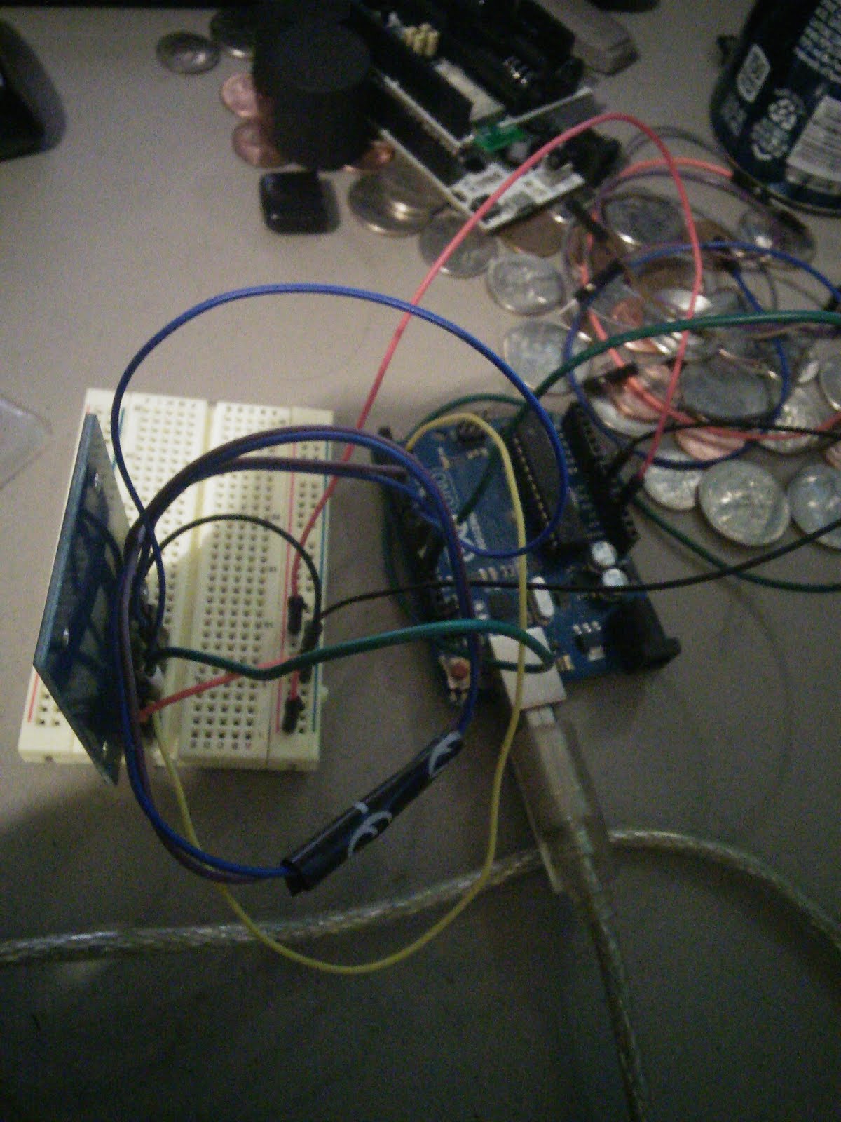
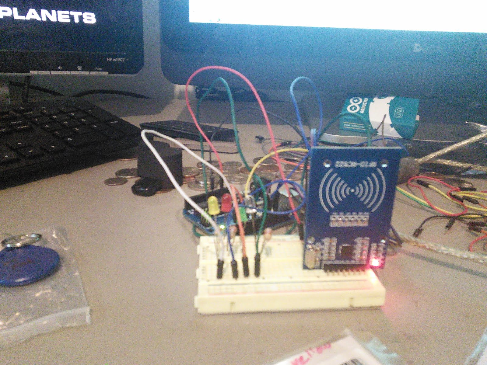
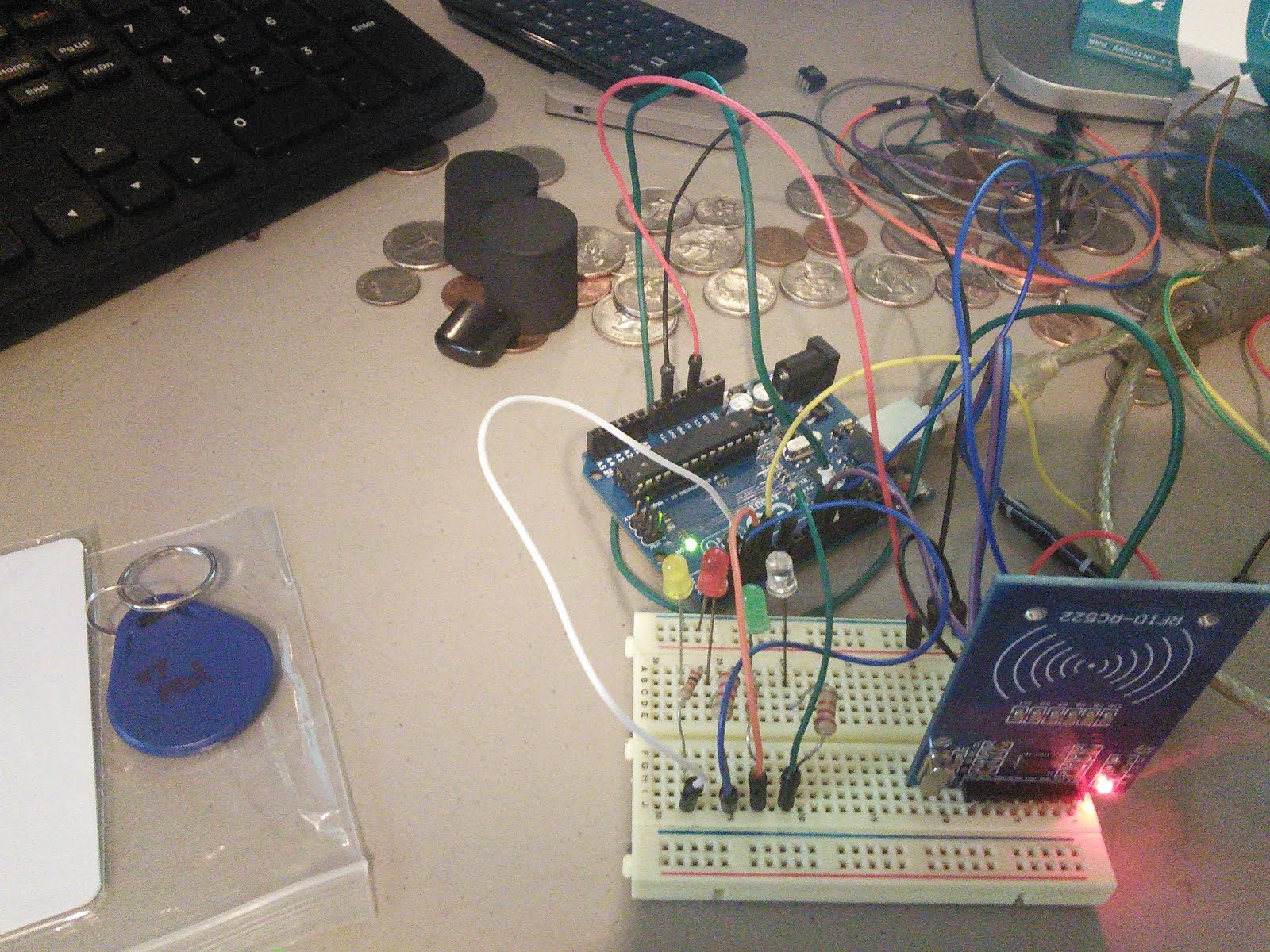
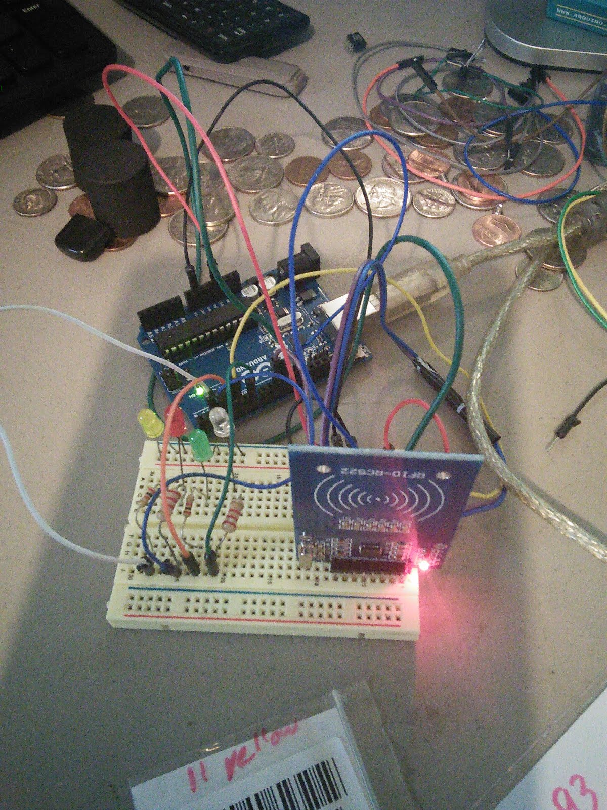
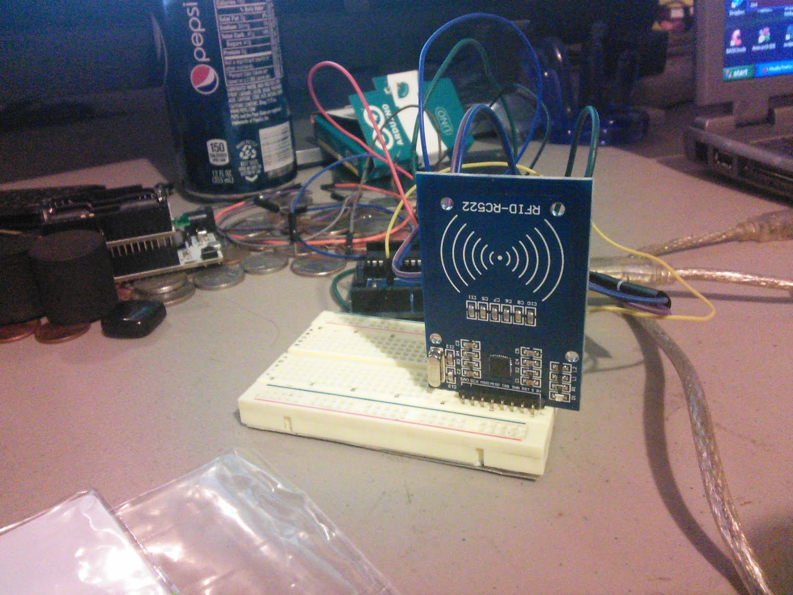
Some pictures of my setup:


20140227 FS1000a 315mhz RX/TX pair

Feb 27, 2014
Initial tests of FS1000a 315mhz RX/TX pair:
This document seems to be relevant to these transmit and receivers.
http://ardumarket.com/en/transmisors/transmisor-rf-fs1000a-330-443mhz-arduino-pic-id19.html
You also need the library from here:
http://www.open.com.au/mikem/arduino/VirtualWire/VirtualWire-1.14.zip
The library contains the sketches found on the page, with the exception that they don’t set the
RX or TX pin
vw_set_tx_pin(3);
vw_set_rx_pin(3);

Also the receiver sketch seems to be a bit different - the example in the library prints out HEX codes.  For the most part these are very simple to use - one Arduino is setup to send information, the other is setup to receive that information - and do something with it.
Modulation type is ASK - or Amplitude Shift Keying - This type of modulation is like AM radio for data So it has some of the same weaknesses and strengths of AM. For more information see:
http://en.wikipedia.org/wiki/Amplitude-shift_keying

Finding a distance for them was a little harder, but as near as I can figure
40 meters or 131 feet indoors, 100 meters or 328 feet in the open.  I tested at about 60 feet inside and it worked without a problem.  Range seems to be dependant on how much voltage you put on the transmitter - from what I
found the TX board can handle between 3 to 12v - with 5v being normal - I don’t know if I trust 12v in this figure, as I only found a couple of sites that said it, and the TX boards were not the same board we have. Better to be safe then sorry and go with 5v.

Like finding a range for these, finding a speed wasn’t as easy as it should be - most sites say between 4800 and 9600 baud work well. A couple of sites say they can go faster, but fastermay cause unreliable data (or no data at all). One site even said that speed was dependant on distance (I don’t think that is right given the type of modulation this uses, but maybe). The sites that have 480 to 9600 baud listed say that it’s a reliable low speed for general use such as reading sensor data.

Impressions of this it would make a good low power data sender for a remote sensor, only takes up one pin, and is really simple to use.

Other information (But not sure if the RX/TX board are the same as what we have):
https://www.sparkfun.com/datasheets/RF/KLP_Walkthrough.pdf
http://www.seeedstudio.com/wiki/index.php?title=315Mhz_RF_link_kit
(Pretty sure this is our board)
http://www.seeedstudio.com/depot/315mhz-rf-link-kit-p-76.html

Update: Feb 28 - Maybe this is not as easy as I first thought, the library seems to have some quirky issues - 1st it seems to want to send a “const char *variable”, I’m not really sure what that is. (Found this out by trying to send a tempature variable floating point to it) and the 2nd thing I found is that it doesn’t work on some of the lesser know Arduino like boards.
(have been trying for the past 2 hours to get the library to work with my Squarewear, wearable temperature sensor, only to find it really doesn’t like that hardware at all) Admittedly the squarewear is not an Arduino, it is closely related to one.

Plans this weekend, try some alternative methods of getting these RF devices to work.

Serious Neglecting the Blog!

So, I haven't been using my blog lately, I think the last post was June 2014.
I have been doing a lot of writing in my google drive about Arduino projects, and other micro controller stuff.

I have been meaning to get back to posting on the blog, but just haven't done it.

So over the next few days, I am going to start moving my documents from drive, and posting them here.

and I'm going to start updating the blog more with projects I am doing.

Monday, July 7, 2014

Using the mBuino with Linux


mBuino is a powerful tiny circuit for all your needs... ARM® Cortex™ 50Mhz, UART, SPI, I2C...programmed using the mbed™ online compiler IDE

It currently (as of July 7, 2014) has 9 days left on kickstarter.

https://www.kickstarter.com/projects/1359959821/mbuino-a-programmable-mbed-keychain

I was given one to test out using linux, as it seems that the NXP LPC11U24 has some issues with linux. Namely firmwares get written to the wrong space on the flash drive. They seem to be 4 blocks off.

With some googling and search a solution was found, and I can verify that with a slight modification the solution works.

My initial testing, coping the mBuino Firmware (just in case something happens), I will have a copy of the firmware that was installed by The OutrageousCircuits team at GHI Electronics.

But I can confirm that it will work with linux, using the DD command.
There are a couple of things you'll need to be aware of before you get started, and a couple of WARNINGS!

Until, I or someone else can get a script written to automate this process, you'll need to know the mount point of the drive.
 One of the easier ways to find this is the DF command:

lfmiller@lfmiller-Inspiron-One-2330 ~/Downloads $ df -h | grep "CRP DISABLD"

/dev/sdb         32K   32K     0 100% /media/lfmiller/CRP DISABLD
lfmiller@lfmiller-Inspiron-One-2330 ~/Downloads $

You could also grep "32K" if you want anyways you'll need the mount point, in my case it's "/dev/sdb" this time around. Also make a note of the directory, you'll need this to erase the current firmware.bin file, and that is what we will do
next. Erase the firmware.bin file that is on the drive, ***WARNING*** THIS STEP CAN NOT BE SKIPPED, if you skip it it will cause problems * See my notes below *

rm "/media/lfmiller/CRP DISABLD/firmware.bin"

So now you have a blank (empty) device. Now we want to put a new firmware on it.
issue this command:
sudo dd if=firmwaretoupdate.bin of=/dev/sdb seek=4

lfmiller@lfmiller-Inspiron-One-2330 ~/Desktop $ sudo dd if="mbunio factory firmware.bin" of=/dev/sdb seek=4
[sudo] password for lfmiller:
64+0 records in
64+0 records out
32768 bytes (33 kB) copied, 0.014345 s, 2.3 MB/s
lfmiller@lfmiller-Inspiron-One-2330 ~/Desktop $

 The very last step is to wait, I've found that there is a very large write delay, and it takes a while for the firmware to update. This seems to be a limitation of linux, as when I tried this with a Windows box, I did not have a delay issue.

2nd ***** WARNING *****
I have had to wait anywhere from 20 secs to 45 secs.
if you don't wait, it will fail, and the old firmware will still be on the device.

If you forget the sudo in the dd command you'll get something like this:
lfmiller@lfmiller-Inspiron-One-2330 ~/Desktop $ dd if="mbunio factory firmware.bin" of=/dev/sdb seek=4
dd: opening ‘/dev/sdb’: Permission denied
lfmiller@lfmiller-Inspiron-One-2330 ~/Desktop $

Bash Shell script:
https://github.com/kd8bxp/mBuino_Linux_uploader
  1. This is a quick dirty script, run it with the sudo command IE: sudo ./uploadfirmware.sh
    run it in the directory that the new firmware is in. Make sure it has execute rights
  2. It doesn't do a whole lot of error checking at this point, and my brain is getting to tired to figure it. It will fail if the mBuino is not plugged in, or not in upload mode
  3. It will not ask you to confirm, it will just do it, so be sure.
  4. It will look for the newest firmware (bin file), that is the file it will upload.
  5. It will tell you the mount points that you need if something does go wrong
  6. It was tested on a few different firmwares, and worked, each time.
  7. It has a sleep delay of 30 seconds, and prompts you to not remove the device before hand, see my blog for details on that.
  8. Fork this and fix it up :-)

** NOTES:

 Here are a few things I've found that are a bit quirky, but could cause issues.

I forgot to erase the old firmware once (and then I did it again to duplicate the results) - What ended up happening, is my linux box couldn't decide what the device was, and didn't mount it, thou it did show it in the drives list, it did not show it as "CRP DISABLD", and refused to do anything with it.
I ended up rebooting the computer, holding the reset button again, and the drive appeared as it should. Erased the firmware, and put a new firmware on it,
 I still had to wait for a while, but this time the reset button didn't work, I had to remove power and plug it back in. This worked at least for me.

It's very important to note that this also happened to me when I put a firmware that had an error on it, I did this on purpose as well, Something similar happened, but this time I was able to remount the device and make changes.

I've done limited tested so far, and hope to update this more over time.  And I hope to get a more automated way to update written soon.


Sunday, June 1, 2014

Where to Start! FPGA, PSOC?

Ok, so I was looking at some kickstarter campaigns again. And came across this:
https://www.kickstarter.com/projects/13588168/papilio-duo-drag-and-drop-fpga-circuit-lab-for-mak

I read it, and thought, wow, that's pretty neat.
And so I had to find out more.
So if you don't already know a FPGA is a Field-programmable gate array. And the way I understand it (which isn't that much really) IS it's all digital, and it's all logic based like on AND, OR, NOT gates, but using these you can "build" timers, switches, computers, and just about anything that uses logic gates. They are on a signal chip, or sometimes a couple of chips.

Well, that is really all I know about these, they sound completely amazing, and I'm wondering just what they really can do if there were millions of them together (Yup, I'm thinking of building Data, come on I can't be the only one who has thought this).

Anyways, FPGA are made by a few different companys, Xilinx, Altera, Lattice, Actel, Achronix, and that is just a few.
The Papilio uses a Spartan 6.

OK, good so far right? These devices seem to be all over the place in price, I've found a few Altera boards on ebay for as little as $15 bucks from China. But typically the prices seem to sit around $45 to ???? (Yup I've seen a few board that go into the 4 digitals a few, very few, but they are out there)

And other then finding boards and manufacturers, I'm really no more along to understanding how to use or program these boards. Speaking of programming,
some of the boards seem to use JTAG, some FTDI (Serial), some "emulate" either JTAG or FTDI using USB.
They all seem to use VHDL or Verilog (or a combination of the two), it also seems that each board manufacture may or may not have a variation of VHDL or use it's own IDE.

There are some but not many tutorials on how to use these, Papilio does have a descent amount of tutorials. So I have been leaning toward one of those boards, but it's hard to make a descision with out a whole lot of information.

 Cost isn't the only factor here, how ever it is a big factor, so a lower cost board that is just as capable as it's pricey brothers would be better. 

Here is what I found, and what I don't understand:
Papilio One 250K - $38 marked down from $50 - Ok I get it doesn't have much ram I guess IS that important for one of these? OR is it all about the processor? and is processor even the right word for these?
Processor: Xlinx XC3S250E and 4Mbit SPI Flash memory
easy introduction to FPGA, digital electronics, and system on a chip design
easily add new functionality with wings that snap onto the board (OK? So these are like Arduino shields from what I gather, and seem to only be offered from Papilio and only work on Papilio - Appears the Papillios don't have anything on board other then just what they need to work)
Two-Channel USB connection for JTAG and Serial Communications (OK does this mean I don't need a JTAG programmer? it's not real clear, but I'm assuming that the board is USB/JTAG emulation)
Four independent power rails at 5v, 3.3v, 2.5v, and 1.2v Ok this might come in handy for something
Power supplied by a power connector or USB
Input Voltage (recommended) 6.5 to 15v (IT doesn't say, but I'm pretty sure this has to be DC)
48 I/O lines
Papilio One 500K - $65 marked down from $80 - Big price dereference here and I'm not sure what the real differences are. So lets look:
Processor: Xlinx XC3S500E and 4Mbit SPI flash memory (Ok, so it's a different processor, but is it better or worse, I don't know I don't have enough info)

Everything else looks like it's the same as above.

 Papilio Pro - $85 marked down from $100, but this looks like a very different board to me.
Processor: Spartan 6 LX8 FPGA
high efficiency LTC3419 step down dual voltage regulator
dual channel FTDI FT2232 USB 2.0 Full speed interface
64MBit micron MT48LC4M16 SPI Flash
48 I/O pins arranged in a Papilio Wing form factor
32mhz crystal oscillator

I don't know if this is good or bad for this board, I really don't understand what it can or can't do, and I don't know why it's different from the other two boards.

Papilio also has that kickstarter campaign running.

So a couple of other boards I was looking at:

 Elbert V2 - Spartan 3A FPGA development board.
Spartan XC3S50A in TQG144 package (Similar boar as the Papilio 50K?)

16Mb SPI flash memory, USB 2.0 interface for on-board flash programming, FPGA configuration via JTAG and USB.
8 LEDs, Six Push Buttons and 8 way DIP switch for user defined application,
VGA output, stereo audio out, Micro SD card adapter, three seven segment displays, 39 I/O lines, on-board voltage regulators for single power rail operation.

OK,  I didn't tell you the price for all this: $30 bucks.


The Numato Labs website looks like it has the information for this board, but doesn't really look like it has a tutorial for using FPGA - So that leaves the question will any tutorial work (IE: the one from Papilio?) Will any software work, IE: if I want to use the pac-man game from papilio will it work on this board?

I'm thinking this board is better in a lot of ways and worse in some other ways.

Cost wise, seems to be better (but maybe not, I don't know enough to know if I'm looking at an old processor or what)
But it does have a lot of "extras" on board, is all that needed? I would have to say yes and no, and here's why. IF you aren't going to use the 7 segment display it's just taking up room that could be used for something you are going to use.
BUT on the other hand you don't have to buy anything extra to get something useful working right out of the box either.
Papilio has what they call wings, including some "mega-wings", Wings seem to range anywhere from a $5 - 8 dollars to $15 - $20 dollars,
"mega-wings" on the other hand seem to go from $25 to $150 dollars, I will say thou they do have a megawing arcade system that is very reasonable price
The nice thing about Papilio is if you don't need it you don't pay for it, but it ends up costing more in the long term.
Elbert V2 vs The Papilio boards:
Elbert 39 I/O pins - Papilio 48 I/O pins - ok I think this is probably a toss up, you lose 9 pins with the Elbert, but if you add any wings to the papilio you lose pins (and you'll almost certainly have to add things to the Papilio to make it useful)


As I sit and write this document, I am starting to wonder if the Elbert wouldn't be the board to buy. Then again I don't have enough information

But you've made it this far, and so have I - My title said FPGA and PSOC!
Let's talk about PSOC so while I was trying to find out more and FPGA I came across the Cypress CY8CKIT-042 PSoC 4 Pioneer Kit - only $25 bucks
Like FPGA there appears to be a lot of different types of PSoc controllers, unlike FPGA Cypress seems to be the only one who makes them. I kind of take that back, there is something call FreeSoc (But I think Cypress still makes the chip for that project)

So PSoC is Programmable System on Chip, and they are "mixed-signal" arrays, and there is a micro controller that controls the array I guess, I'm not sure how they work. Supposedly these are easier to learn how to use if you only have a micro-controller background.
These can do both analog and digital I/O. From what I gather they are similar to FPGA but are very different to use

So I don't know where to get started in something that is more then a  micro-controller, and less then "Commander Data", but might get me a "Data" one day.

The way either sound it sounds like fun times, and a great chance to learn something new.

Any helpful info would be - well helpful!

Wednesday, January 29, 2014

Robot's of the Future are based on Apple II computers! WOW!!!!!!

After seeing this blog: Terminator: Do Robots Think in Apple II source code http://mentalfloss.com/article/15832/terminator-do-robots-think-apple-ii-source-code I got to think about it, and I saw another robot that must at least think in Apple II source code - at least his processor would support that idea.
Of course you all know the Apple II has a MOS 6502 processor right, so I think all robots in the future must be made from our old Apple II machines.... :-)

Wednesday, September 19, 2012

The Robot Project!

It's Sep 19, 2012 - And it's been about 2 months since I started turning an electric chariot (A FAKE Segway) into a robot, this project started out to be a robotic lawn mower, and since it was started I got a real robot lawn mower, so I don't think I want to make this into one any more. I'm not really sure what it will become, but I thought it's been long enough and lots of stuff have happened I felt I needed to document the journey. So this is what I used as the base, mine was blue, and a slightly different model, but they are all pretty much the same. One of the first things that I wanted to do was do a tear down of the chariot and find out just what I was looking at to use. So below is the motor controller, made in China, but that is really about all we were able to find out about it, It's a single controller, but drives both wheels (I should that both wheels do the same thing, in other words, forward drives both wheels forward. there is no left or right control) With that being said, you can see the large relay in the middle, that is used for reverse, and to turn one or the other wheels off. Unfortunately, there is no way to make one wheel go forward and the other to go backward, at least with this controller. The wheels themselfs are the motors, simple 36v DC motor, they are regenerative motors, and it looked like they are setup to feed back into the battery if the break is engaged. Speaking of break, the motor control does have a full stuff electric break, which worked really well, almost too well when there is no weight on the frame. So here is the frame with the motors/wheels, and after I removed the steering off the back wheels and made them free spin (360 degree). And there are 2 or 3 videos of me getting the wheels working with out the "controls" that it came with, really it's a lot of simple switches, So I decided to go ahead and use the controller that it came with, and I wanted to keep the project "cheap" There are also a couple of video showing how I figured out how it did turn one or the other wheels on or off, if one of the wheels is off it becomes a free wheel, and depending on the surface it's sitting on depends on just how much that wheel turns My controller of choice was/is the Parallax Basic Stamp, If you go back and look at some of my video, you can see me playing around with the Stamp, it's easy to use, fairly low cost, and if used in quite a few robots, I also ordered a few arduino relays (12 total, even thou I really only need 6) These are coming from China, cost wise they were very cheap, time wise, they did take a while to get here. And I got extras because what if one failed, I would have to wait again for a replacement, no I have a replacement. Meanwhile I started to program the stamp, and do a basic lay-out of what and where things should be hooked up. The picture below shows the relays and the stamp on a board on the frame of the chariot. It was about this time thou that I came across an Ambrogio robotic lawn mower, and that is when this changed from a lawn mower to just a really cool robot to play with! In the picture above you can see the relays, (3 of which are no being using, more on this later), the basic stamp board, and a 2nd breadboard - the 2nd breadboard has a LM358A Dual Operational Amplifier, this when using a Pulse Width modulation signal from the stamp can be used to generate 5v which is used then to drive the motor controller - 5v will give max speed, the PWM can be adjusted and various voltages come out, 0v volt = stop, and anything between 0 to 5 will control the speed of the wheels. At this point, the LM358A circuit didn't work, and we finally decided that it really did need 12v like the diagram said it did, We did end up destroying one side of the Op Amp as well. A ping sensor was also added at some point with in this time frame. and a simple real word test was done, at this time I was using a weak battery, but was doing a test, things seemed to work, more or less, but once I put a good main battery on it - it was way too fast. During this test thou I decided that I might need to add a servo for the ping sensor to move, and get better detection. We also added some Voltage regulators at this time, a 12v, 9v and 5v were all added. The LM358A was placed on it's own breadboard, and piece of wood, it was mounted behind the stamp (Unfortunately I can't find any pictures of this, thou there are some videos with it in this configuration), Also mounted the USB connector for the stamp, and using a USB extension cable to program it now. At some point, we decided that we also needed more amperes to power everything, both the 9v and later the 5v had transistors added to them for just that reason. This ended up causing hugh problems thou, what my partner didn't realize is that the transistor where grounding out on one of the positive pins, And we went though many burt wires, and lots of archs and sparks. It took almost a week to get it back to "normal", and I ended up doing an almost complete rebuild. At one point I did think I fried the basic stamp board, but luckily it is working just fine. The above video was just after the rebuild. This was also after a rebuild, during the time of all the archs and sparks I beleive we ending up rebuilding this twice or more, I did move things around more thou, not really a complete rebuild. The above video shows a wheel/bench test this is after I got LM358A working, and again I moved some stuff around, removed the servo at this point, but later I moved the ping sensor again and put the servo back on. it was about this time that my Parallax LCD showed up, the LCD has backlight and speaker, this added the many possibility And my ADC0831 analog to digital converter showed up, and a very simple voltage meter was added, using a simple voltage divider. This was also the 2nd time during this project that I blow something up...Its a good thing I ordered two ADC0831, they really don't like having 36v applied to the input. I also mounted the LCD, and moved the board from behind the stamp, to ontop of the Stamp (For like a two layered effect), moved the Ping Sensor and added the servo again. I was having some issues with the servo, I thought it was a power issue, but turns out the basic stamp just didn't like a 25+ year old analog servo. At this point however I didn't fix that problem and just disconnected the servo again. I wrote some code for playing a "Battery Dead" and "Unknown Error" sounds using the LCD, and put those sounds into the robot code. About this time, My IR Obstacle Avoidance sensors showed up from China, I haven't added these into the bot yet, I did test them, they work great, are very simple on off switches (If it sees nothing it's on, if it sees something it's off, or is it just the opposite?) Either way I wrote some code, and I am planning on using these from drop off sensors, and yes they did work outside, quite happy with the results, but still need to get them mounted. Which finally brings us up to about last week, I added a Basic Micro Nano8 processor to control the servo, I setup the Stamp to send a high to the Nano8 when the Stamp wants the servo to move, the Nano8 is just will move the stamp to one of three spots, -45 degree, 90 degree, and 45 degree. It just counts the number of highs/low and decides where to move the servo, there is no feedback to the Stamp, the timing on this is a little off, but this is kind of a work in progress and it does work. The Nano8 has 4 I/O lines plus a serial port, the 4 I/O lines can be used for A2D, and 1 of the lines is capable of doing PWM. I have two analog sensors ordered a temperature and a humidity. I also order a couple of serial port buffers so the Nano8 can send the sensor information the Stamp, and the Stamp can decide what to do with it. But for now the Nano8 is only controlling the servo, added the Nano8 appears to have fixed the bouncing issue I was having using this servo with the Stamp. Of course this is still very much a work in progress, I have several things ordered that haven't arrived yet, an accelerometer, humidity and temp sensors. I did order a smaller relay board, and they arrived today, so I am going to replace one of the relay boards with the smaller board. I still need to figure out away to contain it within the yard, and work on getting better speed out of the wheels, or maybe just one speed at this point? Reverse goes at almost full speed, while forward is going to be very slow. I have a lot of videos of the progress on this, alot more then I posted here. http://www.youtube.com/kd8bxp That brings the project current as of Sept 19, 2012, I'll be doing more posts as it progresses, and of course a lot more videos to come! LeRoy, KD8BXP